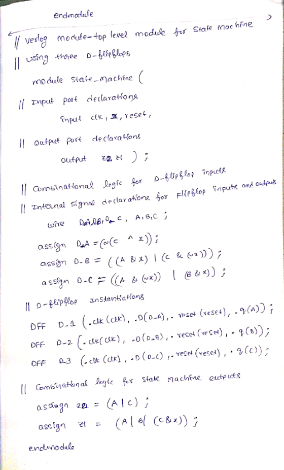
WRITE THE CODE IN VERILOG: Instead of using Registers, USE D
FLIP FLOPS and a clock. Include the logic for a reset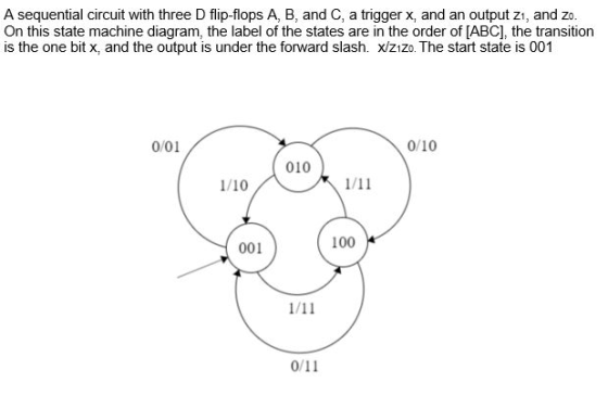
![D Flip Flop Example module DEF (clk, in, out); parameter n = 1; input cik; input (n-1:0) in; output (n-1:0] out; reg (n-1:01](http://img.homeworklib.com/questions/211e8de0-fd3e-11eb-b20a-3b06f423e3bd.png?x-oss-process=image/resize,w_560)
Homework Answers


Add Answer to:
WRITE THE CODE IN VERILOG: Instead of using Registers, USE D
FLIP FLOPS and a clock....
Digital Logic Design Design a 0-9 counter using four D flip flops. The counter should run...
Digital Logic Design Design a 0-9 counter using four D flip flops. The counter should run on the SCLK output of the clock divider. It should have a four-bit binary output that increments from 0 to 9 one step on each clock cycle. When it reaches the value of 9, it should restart a 0 on the next clock cycle. Hint: consider using D flip flops with a reset input and using logic to reset the flip flops when the...
In Verilog, design the circuit below (an upcounter) using 3 D flip flops shown in image2....
 In Verilog, design the circuit below (an upcounter) using 3 D
flip flops shown in image2. To be programmed in Vivado and used on
BASYS3 board
REG3 DO 20 QO DI 01 21 XORZ AND2 D2 Q2 Q2 XORZ cik clock D[2] D[11 DIO D Flip-Flop Flip Flop swin en sw in sw_in clock clock clock 0[2] [11 Q[o]
In Verilog, design the circuit below (an upcounter) using 3 D
flip flops shown in image2. To be programmed in Vivado and used on
BASYS3 board
REG3 DO 20 QO DI 01 21 XORZ AND2 D2 Q2 Q2 XORZ cik clock D[2] D[11 DIO D Flip-Flop Flip Flop swin en sw in sw_in clock clock clock 0[2] [11 Q[o]
Design a counter to count-up from 2 to 5 using 3 D Flip-Flops similar to the...
 Design a counter to count-up from 2 to 5 using 3 D Flip-Flops similar to the following sample: Important Steps: After you simplify D2, D1 and DO by kmap Have a piece of paper to draw it then open iCircuit to design it using BCD If it works well as a counter, copy the design from iCircuit and paste it here. 3-Bit Counter Using D Flip-Flop: The State Equation of D Flip-Flop: Q(t+1)=D(t) => Dn=An Count Up From 3 To...
5.28 The Verilog code in Figure P5.9 represents a 3-bit linear-feedback shift register (LFSR) This type...
 5.28 The Verilog code in Figure P5.9 represents a 3-bit linear-feedback shift register (LFSR) This type of circuit generates a counting sequence of pseudo-random numbers that repeats after 2" - 1 clock cycles, where n is the number of flip-flops in the LFSR. Synthesize a circuit to implement the LFSR in a chip. Draw a diagram of the circuit. Simulate the circuit's behavior by loading the pattern 001 into the LFSR and then enabling the register to count. What is...
7. JK flip-flops are often used to build counters. The JK flip-flop will toggle the original...
 7. JK flip-flops are often used to build counters. The JK flip-flop will toggle the original output value when triggered by the clock signal if both the J.K inputs are connected with a constant "high"(logic 1). Suppose all the JK flip-flops in following Figure are positive edge triggered. The edges of the CLOCK are marked out in the figure. All the Qs have initial value 0. HIGH IFE CLOCK-HCL LK 000 0 0 0 Figure. Counter (a) Sketch the output...
D Flip-Flops Include the symbol and characteristic table of a 1-bit rising edge D flip-flop Write...
D Flip-Flops Include the symbol and characteristic table of a 1-bit rising edge D flip-flop Write a Verilog module called dflipflop to implement a simple one-bit D flip Flop with input of data and clock and 1-bit output data
3. A timing diagram below shows a D Flip-flop and the input clock. Show the transition...
 3. A timing diagram below shows a D Flip-flop and the input clock. Show the transition of the output Q at the positive transitions of the clock signal. Q 1 initially. Clk 4. Implement a 2-bit up-counter using D flip-flops. Show the circuit. 5. Implement a 2-bit down-counter using D flip-flops. Show the circuit. Transitions: 11->10->01->00->11->10->...
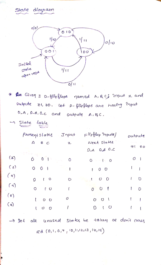
Using D flip-flops, design a Moore circuit that detects the sequence 1100. The circuit outputs I...
 Using D flip-flops, design a Moore circuit that detects the sequence 1100. The circuit outputs I when the sequence 1100 is received and outputs 0 otherwise. Draw the state diagram and state table, and find the D flip-flops input equations and the output equation x- Z Clock Hint: X: 01011 00011001100011 Z: 0 0 0 0 0 0 100000000000
verilog code needed for the counter using the JK flip flop please include the testbench, thanks!...
 verilog code needed for the counter using the JK flip
flop
please include the testbench, thanks!
Successfully completing a System Verilog +80Pts. Implementation showing the full sequence of ABC readouts Pre-Laboratory Exercise: You are to design a counter that will count through a sequence either forward or reverse. You will have two control inputs: Direction, and Reset'. Sequence #2: 000 100 110 111 101001 → 011 010 → 000... {Gray code} When Direction=0 follow the order listed above. When Direction...
verilog code needed for the counter using the JK flip
flop
please include the testbench, thanks!
Successfully completing a System Verilog +80Pts. Implementation showing the full sequence of ABC readouts Pre-Laboratory Exercise: You are to design a counter that will count through a sequence either forward or reverse. You will have two control inputs: Direction, and Reset'. Sequence #2: 000 100 110 111 101001 → 011 010 → 000... {Gray code} When Direction=0 follow the order listed above. When Direction...
Using all D flip-flops and combinational logic (AND/OR/NOT gates only) b) using all T flip-flop...
 using all D flip-flops and combinational logic (AND/OR/NOT gates
only)
b) using all T flip-flops and a multiplexer of size 8:1
Problem 3: (10 pts) Design a synchronous machine (Transition Table, K-maps, Final Equations, Circuit Diagram) that counts through the following sequence in the order shown below. Note, there are no inputs or output variables, so your Q values must reflect the Hex value listed B 74 2 D9 3 0 and repeat a) using all D flip-flops and combinational...
using all D flip-flops and combinational logic (AND/OR/NOT gates
only)
b) using all T flip-flops and a multiplexer of size 8:1
Problem 3: (10 pts) Design a synchronous machine (Transition Table, K-maps, Final Equations, Circuit Diagram) that counts through the following sequence in the order shown below. Note, there are no inputs or output variables, so your Q values must reflect the Hex value listed B 74 2 D9 3 0 and repeat a) using all D flip-flops and combinational...
 In Verilog, design the circuit below (an upcounter) using 3 D
flip flops shown in image2. To be programmed in Vivado and used on
BASYS3 board
REG3 DO 20 QO DI 01 21 XORZ AND2 D2 Q2 Q2 XORZ cik clock D[2] D[11 DIO D Flip-Flop Flip Flop swin en sw in sw_in clock clock clock 0[2] [11 Q[o]
In Verilog, design the circuit below (an upcounter) using 3 D
flip flops shown in image2. To be programmed in Vivado and used on
BASYS3 board
REG3 DO 20 QO DI 01 21 XORZ AND2 D2 Q2 Q2 XORZ cik clock D[2] D[11 DIO D Flip-Flop Flip Flop swin en sw in sw_in clock clock clock 0[2] [11 Q[o]
 Design a counter to count-up from 2 to 5 using 3 D Flip-Flops similar to the following sample: Important Steps: After you simplify D2, D1 and DO by kmap Have a piece of paper to draw it then open iCircuit to design it using BCD If it works well as a counter, copy the design from iCircuit and paste it here. 3-Bit Counter Using D Flip-Flop: The State Equation of D Flip-Flop: Q(t+1)=D(t) => Dn=An Count Up From 3 To...
 5.28 The Verilog code in Figure P5.9 represents a 3-bit linear-feedback shift register (LFSR) This type of circuit generates a counting sequence of pseudo-random numbers that repeats after 2" - 1 clock cycles, where n is the number of flip-flops in the LFSR. Synthesize a circuit to implement the LFSR in a chip. Draw a diagram of the circuit. Simulate the circuit's behavior by loading the pattern 001 into the LFSR and then enabling the register to count. What is...
 7. JK flip-flops are often used to build counters. The JK flip-flop will toggle the original output value when triggered by the clock signal if both the J.K inputs are connected with a constant "high"(logic 1). Suppose all the JK flip-flops in following Figure are positive edge triggered. The edges of the CLOCK are marked out in the figure. All the Qs have initial value 0. HIGH IFE CLOCK-HCL LK 000 0 0 0 Figure. Counter (a) Sketch the output...
 3. A timing diagram below shows a D Flip-flop and the input clock. Show the transition of the output Q at the positive transitions of the clock signal. Q 1 initially. Clk 4. Implement a 2-bit up-counter using D flip-flops. Show the circuit. 5. Implement a 2-bit down-counter using D flip-flops. Show the circuit. Transitions: 11->10->01->00->11->10->...
 Using D flip-flops, design a Moore circuit that detects the sequence 1100. The circuit outputs I when the sequence 1100 is received and outputs 0 otherwise. Draw the state diagram and state table, and find the D flip-flops input equations and the output equation x- Z Clock Hint: X: 01011 00011001100011 Z: 0 0 0 0 0 0 100000000000
 verilog code needed for the counter using the JK flip
flop
please include the testbench, thanks!
Successfully completing a System Verilog +80Pts. Implementation showing the full sequence of ABC readouts Pre-Laboratory Exercise: You are to design a counter that will count through a sequence either forward or reverse. You will have two control inputs: Direction, and Reset'. Sequence #2: 000 100 110 111 101001 → 011 010 → 000... {Gray code} When Direction=0 follow the order listed above. When Direction...
verilog code needed for the counter using the JK flip
flop
please include the testbench, thanks!
Successfully completing a System Verilog +80Pts. Implementation showing the full sequence of ABC readouts Pre-Laboratory Exercise: You are to design a counter that will count through a sequence either forward or reverse. You will have two control inputs: Direction, and Reset'. Sequence #2: 000 100 110 111 101001 → 011 010 → 000... {Gray code} When Direction=0 follow the order listed above. When Direction...
 using all D flip-flops and combinational logic (AND/OR/NOT gates
only)
b) using all T flip-flops and a multiplexer of size 8:1
Problem 3: (10 pts) Design a synchronous machine (Transition Table, K-maps, Final Equations, Circuit Diagram) that counts through the following sequence in the order shown below. Note, there are no inputs or output variables, so your Q values must reflect the Hex value listed B 74 2 D9 3 0 and repeat a) using all D flip-flops and combinational...
using all D flip-flops and combinational logic (AND/OR/NOT gates
only)
b) using all T flip-flops and a multiplexer of size 8:1
Problem 3: (10 pts) Design a synchronous machine (Transition Table, K-maps, Final Equations, Circuit Diagram) that counts through the following sequence in the order shown below. Note, there are no inputs or output variables, so your Q values must reflect the Hex value listed B 74 2 D9 3 0 and repeat a) using all D flip-flops and combinational...
Most questions answered within 3 hours.
-
17. Which of the following best describes a fulfilling life for
Epicurus:
(a) Eat, drink, and...
asked 8 minutes ago -
An ideal analog-to-digital converter has 6 bits and a 1V input
full-scale input voltage. What is...
asked 10 minutes ago -
If a computer which has a 32 bit word has a 34 bit byte
addressable memory...
asked 28 minutes ago -
Group 10 M(II) complexes are often four-coordinate. For Pd and
Pt, these molecules are square planar...
asked 25 minutes ago -
Factors - Analyze factors that contributed to the obsolescence
or dissolution of The Banking Industry, Bank...
asked 31 minutes ago -
he McCumber Corporation data for the current year:
Account
Current
year
Prior
year
Current assets
$76,200...
asked 41 minutes ago -
A ball is tossed from an upper-story window of a building. The
ball is given an...
asked 43 minutes ago -
oceanic ridges represent what percentage of the earths
surface
asked 47 minutes ago -
Biological oxidation of phenylacetic acid is inhibited by
propionic acid present in wastewater. The following data...
asked 58 minutes ago -
It is essential that organizational leaders understand the
competitive, financial, and strategic advantages that can result...
asked 1 hour ago -
Ziegler-Natta Catalysts have been successfully used to
polymerize the following monomers: (select all that apply)
a....
asked 1 hour ago -
User documentation _____.
allows users to prepare overall documentation, such as process
descriptions and report layouts,...
asked 1 hour ago