To be completed on MATLAB. Thanks!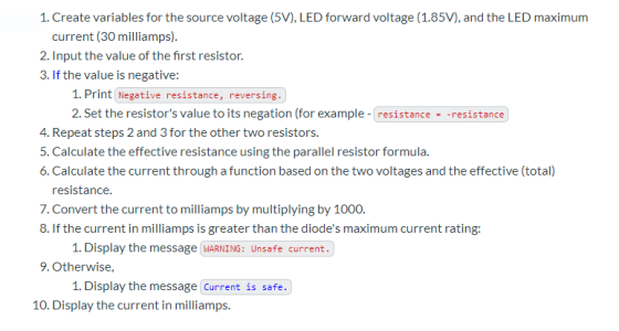
Homework Answers
MATLAB script
clc
clear
close
sv=5; fv=1.85;mc=30;
r1=input('Enter the value of first resistor');
if r1<0;
disp('Negative resistance,reversing')
r1=-r1;
end
r2=input('Enter the value of first resistor');
if r2<0;
disp('Negative resistance,reversing')
r2=-r2;
end
r3=input('Enter the value of first resistor');
if r3<0;
disp('Negative resistance,reversing')
r3=-r3;
end
ref=(r1*r2*r3/(r1*r2+r2*r3+r3*r1));
c=ref*(sv+fv)*1000;
if c>mc
disp('WARNING:Unsafe current')
else
disp('current is safe')
fprintf('current in function is %g\n',c)
end
Result
Enter the value of first resistor 1e-5
Enter the value of first resistor -2e-5
Negative resistance,reversing
Enter the value of first resistor 10e-5
current is safe
current in function is 0.0428125 milliamps
Add Answer to:
To be completed on MATLAB. Thanks!
1. Create variables for the source voltage (5V), LED forward...
Pease answer questions 4 and 5! Thank you so much! 4. Connect the 2nd resistor in...
 Pease answer questions 4 and 5! Thank you so much!
4. Connect the 2nd resistor in parallel with the 1st
resistor and connect that combination to the battery.
Measure
the following:
The
current passing through the R1, I1 = ___0.0058____ A
The
current passing through the R2, I2 = ___0.0031____ A
The
current supplied by the battery, I = ___0.0092____ A
Calculate I1 + I2 = ____________ A
Is the following statement true? I = I1 +...
Pease answer questions 4 and 5! Thank you so much!
4. Connect the 2nd resistor in parallel with the 1st
resistor and connect that combination to the battery.
Measure
the following:
The
current passing through the R1, I1 = ___0.0058____ A
The
current passing through the R2, I2 = ___0.0031____ A
The
current supplied by the battery, I = ___0.0092____ A
Calculate I1 + I2 = ____________ A
Is the following statement true? I = I1 +...
Q1. You are given a 12 V DC power supply. You are expected to develop a voltage divider to achieve a voltage of no...
 Q1. You are given a 12 V DC power supply. You are expected to develop a voltage divider to achieve a voltage of nominal 5V value using a pair of resistors from the E 12 range, with the restrition that you are not expected to draw a current of more than 1 mA from the 12 V DC supply i. Develop a simple circuit showing the possible values for each resistor pair, and the range of the DC output possible...
USE MATLAB PLEASE Q4) (15 pts) An RLC circuit with an alternating voltage source is shown....
 USE MATLAB PLEASE
Q4) (15 pts) An RLC circuit with an alternating voltage source is shown. The source voltage v, is given by vs = Vm sin(@dt), where on = 21fd, in which fo is the driving frequency. The ampli- tude of the current, 1, in this circuit is given by: Vm I = = R-+[waL-1/(waC)]* where R and C are the resistance of the resistor and capacitance of the capacitor, respectively. For the circuit in the figure C =...
USE MATLAB PLEASE
Q4) (15 pts) An RLC circuit with an alternating voltage source is shown. The source voltage v, is given by vs = Vm sin(@dt), where on = 21fd, in which fo is the driving frequency. The ampli- tude of the current, 1, in this circuit is given by: Vm I = = R-+[waL-1/(waC)]* where R and C are the resistance of the resistor and capacitance of the capacitor, respectively. For the circuit in the figure C =...
Notes for lab dc02-Resistors and the Color Code will skip are Part 2 e, g: Part 4; Exercises 2, 4,5,6 an...
 Notes for lab dc02-Resistors and the Color Code will skip are Part 2 e, g: Part 4; Exercises 2, 4,5,6 and 3. It is important to answer the exercises correctly in each labl you should include the appropriate prefix for the unit in the Numerical Value We will not be Volt using the Volt-Ohm meter (VOM) for this lab, so skip the parts that ask for VOM measurements. The parts we You do need to complete Exercises1 Note that in...
Could you please show me how I can drw those circuits. please using (NI Multisim 14)...
 Could you please show me how I can drw those circuits.
please using (NI Multisim 14)
Optocoupler Objectives Use an ohmmeter to determine the condition of the optoisolator. Observe the operation of an optocoupler. Determine the maximum frequency response of the optocoupler. Required Materials (1) Dual DC power supply (1) Function generator (1) Oscilloscope (2) Multimeters (1) Optocoupler (ECG3040) (1) 3.9ΚΩ resistor (1) 220 resistor Introduction An optoisolator is a hybrid integrated circuit that contains an LED on one side...
Could you please show me how I can drw those circuits.
please using (NI Multisim 14)
Optocoupler Objectives Use an ohmmeter to determine the condition of the optoisolator. Observe the operation of an optocoupler. Determine the maximum frequency response of the optocoupler. Required Materials (1) Dual DC power supply (1) Function generator (1) Oscilloscope (2) Multimeters (1) Optocoupler (ECG3040) (1) 3.9ΚΩ resistor (1) 220 resistor Introduction An optoisolator is a hybrid integrated circuit that contains an LED on one side...
+Vs- -V 8 LBC BLS 11 Als 12 11 E Loop (1) R2 Loop (2)R3 L2...
 +Vs- -V 8 LBC BLS 11 Als 12 11 E Loop (1) R2 Loop (2)R3 L2 GI G2 G3 Figure (6.1): Two loop circuit with two emfs 3 B A R1 R2 R3Z GI G2 G3 Figure (6.2): Series and parallel resistors + Vs - B 11 A 13 С 12 11 R1 Red R3 GI G2 G3 Figure (6.3): Series and parallel resistor circuit 4 V. ANALYSIS: Procedure (1): Two Loop Circuit 1. Verify KLR for each loop by...
14) Which of the following is NOT a typical electrical component? A) Resistor B) Capacitor C)...
 14) Which of the following is NOT a typical electrical component? A) Resistor B) Capacitor C) Megatron Inductor E) Transformer D) 23) Convert 6.8 x 10⁻⁵ W to the closest standard metric prefix. A) 68 °W B) 0.68 uW C) 680 uW D) 6.8 uw 24) Convert 3.95 x 10⁻⁴ A to the closest standard metric prefix. A) 3.95 mA 39.5 mA 0.395 mA D 395 mA Convert the following: 25) 2 x 10⁻³ Amp = A) 2 microamps 2...
I need aome help with this part of my lab. thank you! Kirchoff's Laws 4. Now...
 I need aome help with this part of my lab. thank you!
Kirchoff's Laws 4. Now click on this link, which is another circuit I modified and created for this lab: http://tinyurl.com/y8toda84 A. Do not Click run/Stop. This is a circuit that has elements that are neither series nor parallel, as well as multiple voltage sources. The best way for us to analyze this circuit is to use Kirchoff's laws. From the text here are Kirchoff's laws: 1) The sum...
I need aome help with this part of my lab. thank you!
Kirchoff's Laws 4. Now click on this link, which is another circuit I modified and created for this lab: http://tinyurl.com/y8toda84 A. Do not Click run/Stop. This is a circuit that has elements that are neither series nor parallel, as well as multiple voltage sources. The best way for us to analyze this circuit is to use Kirchoff's laws. From the text here are Kirchoff's laws: 1) The sum...
The six-bus system shown in Figure 1 will be simulated using MATLAB. Transmission line data and b...
 The six-bus system shown in Figure 1 will be simulated using MATLAB. Transmission line data and bus data are given in Tables 1 and 2 respectively. The transmission line data are calculated on 100 MVA base and 230 (line-to-line) kV base for generator. Tasks: 1. Determine the network admittance matrix Y 2. Find the load flow solution using Gauss-Seidel/Newton Raphson method until first iteration by manual calculation. Use Maltab software to solve power flow problem using Gauss-Seidel method. Find the...
02 +Vo D3 Rgare 18 Circuit for Problem 1 Analysis 1. Copy the circuit of Figure 1.8 and sketch the ow of pesitive curment throughout the entire circuit for o>0. Repeat for n ce 2....
 02 +Vo D3 Rgare 18 Circuit for Problem 1 Analysis 1. Copy the circuit of Figure 1.8 and sketch the ow of pesitive curment throughout the entire circuit for o>0. Repeat for n ce 2. Plot two periods of nlt) and s) for each of the thee input wave shown in Figune 17 on page 37 fom output t (a) Feak value, and b) Eflective DC value, also known as RMS value NotTE These and are therefore optional 4. Determine...
 Pease answer questions 4 and 5! Thank you so much!
4. Connect the 2nd resistor in parallel with the 1st
resistor and connect that combination to the battery.
Measure
the following:
The
current passing through the R1, I1 = ___0.0058____ A
The
current passing through the R2, I2 = ___0.0031____ A
The
current supplied by the battery, I = ___0.0092____ A
Calculate I1 + I2 = ____________ A
Is the following statement true? I = I1 +...
Pease answer questions 4 and 5! Thank you so much!
4. Connect the 2nd resistor in parallel with the 1st
resistor and connect that combination to the battery.
Measure
the following:
The
current passing through the R1, I1 = ___0.0058____ A
The
current passing through the R2, I2 = ___0.0031____ A
The
current supplied by the battery, I = ___0.0092____ A
Calculate I1 + I2 = ____________ A
Is the following statement true? I = I1 +...
 Q1. You are given a 12 V DC power supply. You are expected to develop a voltage divider to achieve a voltage of nominal 5V value using a pair of resistors from the E 12 range, with the restrition that you are not expected to draw a current of more than 1 mA from the 12 V DC supply i. Develop a simple circuit showing the possible values for each resistor pair, and the range of the DC output possible...
 USE MATLAB PLEASE
Q4) (15 pts) An RLC circuit with an alternating voltage source is shown. The source voltage v, is given by vs = Vm sin(@dt), where on = 21fd, in which fo is the driving frequency. The ampli- tude of the current, 1, in this circuit is given by: Vm I = = R-+[waL-1/(waC)]* where R and C are the resistance of the resistor and capacitance of the capacitor, respectively. For the circuit in the figure C =...
USE MATLAB PLEASE
Q4) (15 pts) An RLC circuit with an alternating voltage source is shown. The source voltage v, is given by vs = Vm sin(@dt), where on = 21fd, in which fo is the driving frequency. The ampli- tude of the current, 1, in this circuit is given by: Vm I = = R-+[waL-1/(waC)]* where R and C are the resistance of the resistor and capacitance of the capacitor, respectively. For the circuit in the figure C =...
 Notes for lab dc02-Resistors and the Color Code will skip are Part 2 e, g: Part 4; Exercises 2, 4,5,6 and 3. It is important to answer the exercises correctly in each labl you should include the appropriate prefix for the unit in the Numerical Value We will not be Volt using the Volt-Ohm meter (VOM) for this lab, so skip the parts that ask for VOM measurements. The parts we You do need to complete Exercises1 Note that in...
 Could you please show me how I can drw those circuits.
please using (NI Multisim 14)
Optocoupler Objectives Use an ohmmeter to determine the condition of the optoisolator. Observe the operation of an optocoupler. Determine the maximum frequency response of the optocoupler. Required Materials (1) Dual DC power supply (1) Function generator (1) Oscilloscope (2) Multimeters (1) Optocoupler (ECG3040) (1) 3.9ΚΩ resistor (1) 220 resistor Introduction An optoisolator is a hybrid integrated circuit that contains an LED on one side...
Could you please show me how I can drw those circuits.
please using (NI Multisim 14)
Optocoupler Objectives Use an ohmmeter to determine the condition of the optoisolator. Observe the operation of an optocoupler. Determine the maximum frequency response of the optocoupler. Required Materials (1) Dual DC power supply (1) Function generator (1) Oscilloscope (2) Multimeters (1) Optocoupler (ECG3040) (1) 3.9ΚΩ resistor (1) 220 resistor Introduction An optoisolator is a hybrid integrated circuit that contains an LED on one side...
 +Vs- -V 8 LBC BLS 11 Als 12 11 E Loop (1) R2 Loop (2)R3 L2 GI G2 G3 Figure (6.1): Two loop circuit with two emfs 3 B A R1 R2 R3Z GI G2 G3 Figure (6.2): Series and parallel resistors + Vs - B 11 A 13 С 12 11 R1 Red R3 GI G2 G3 Figure (6.3): Series and parallel resistor circuit 4 V. ANALYSIS: Procedure (1): Two Loop Circuit 1. Verify KLR for each loop by...
 14) Which of the following is NOT a typical electrical component? A) Resistor B) Capacitor C) Megatron Inductor E) Transformer D) 23) Convert 6.8 x 10⁻⁵ W to the closest standard metric prefix. A) 68 °W B) 0.68 uW C) 680 uW D) 6.8 uw 24) Convert 3.95 x 10⁻⁴ A to the closest standard metric prefix. A) 3.95 mA 39.5 mA 0.395 mA D 395 mA Convert the following: 25) 2 x 10⁻³ Amp = A) 2 microamps 2...
 I need aome help with this part of my lab. thank you!
Kirchoff's Laws 4. Now click on this link, which is another circuit I modified and created for this lab: http://tinyurl.com/y8toda84 A. Do not Click run/Stop. This is a circuit that has elements that are neither series nor parallel, as well as multiple voltage sources. The best way for us to analyze this circuit is to use Kirchoff's laws. From the text here are Kirchoff's laws: 1) The sum...
I need aome help with this part of my lab. thank you!
Kirchoff's Laws 4. Now click on this link, which is another circuit I modified and created for this lab: http://tinyurl.com/y8toda84 A. Do not Click run/Stop. This is a circuit that has elements that are neither series nor parallel, as well as multiple voltage sources. The best way for us to analyze this circuit is to use Kirchoff's laws. From the text here are Kirchoff's laws: 1) The sum...
 The six-bus system shown in Figure 1 will be simulated using MATLAB. Transmission line data and bus data are given in Tables 1 and 2 respectively. The transmission line data are calculated on 100 MVA base and 230 (line-to-line) kV base for generator. Tasks: 1. Determine the network admittance matrix Y 2. Find the load flow solution using Gauss-Seidel/Newton Raphson method until first iteration by manual calculation. Use Maltab software to solve power flow problem using Gauss-Seidel method. Find the...
 02 +Vo D3 Rgare 18 Circuit for Problem 1 Analysis 1. Copy the circuit of Figure 1.8 and sketch the ow of pesitive curment throughout the entire circuit for o>0. Repeat for n ce 2. Plot two periods of nlt) and s) for each of the thee input wave shown in Figune 17 on page 37 fom output t (a) Feak value, and b) Eflective DC value, also known as RMS value NotTE These and are therefore optional 4. Determine...
Most questions answered within 3 hours.
-
The free energy change for the following reaction at 25 °C, when
[Sn2+] = 1.17 M...
asked 46 minutes ago -
An MNE is this kind of industry when competition in one country
is essentially independent of...
asked 2 hours ago -
. For this set of questions, determine what
proportion of a normal distribution is located betweeneach...
asked 2 hours ago -
A college student is employed as a door-to-door newspaper
salesman. Historical data suggests that the student...
asked 3 hours ago -
MATLAB HW 11 problem using Switch Case and Input commands
Write a script file that calculates...
asked 3 hours ago -
Considering gravitational time dilation, calculate the time that
passes in Earth’s surface while 1 hour passes...
asked 4 hours ago -
Minitab Problem: Take the Lake Hume June rainfall data and find
use the processes outlined in...
asked 5 hours ago -
X Company is trying to decide whether to continue using old
equipment to make Product A...
asked 5 hours ago -
IN PYTHON ONLY !! Program 2: Re-work
program #5 (WeeklyHours) from the previous assignment such that...
asked 5 hours ago -
The average length of time between arrivals at a turnpike
toll-booth is 26 seconds. What is...
asked 7 hours ago -
(a) A piston at 6.1 atm contains a gas that occupies a volume of
3.5 L....
asked 8 hours ago -
Please answer true or false. Words
cannot be changed or added in to make it true...
asked 8 hours ago