


Homework Answers

Add Answer to:
Q1. The values of the difference amplifier in figure 1 are Ao 5x 10⁵, Rı =...
Q1. The values of the difference amplifier in figure 1 are Ap - 5 x 10⁵,...
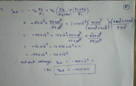
 Q1. The values of the difference amplifier in figure 1 are Ap - 5 x 10⁵, RI 5k2, RF 50ks2. R, = 2M2. and Rz-20M2. The input voltages are vb 5mV and va--15mV. Find the out voltage vo. (5 Points) RF 는 Ra
Laboratory 1: operation amplifier characteristics A. Objectives: 1. To study the basic characteri...
 thanks
Laboratory 1: operation amplifier characteristics A. Objectives: 1. To study the basic characteristics of an operational amplifier 2. To study the bias circuit of an operational amplifier B. Apparatus: 1. DC Power supply 2. Experimental board and corresponding components 3. Electronic calculator (prepared by students) 4. Digital camera (prepared by students for photo taking of the experimental results) 5. Laptop computer with the software PicoScope 6 and Microsoft Word installed. 6. PicoScope PC Oscilloscope and its accessories. 7. Multimeter...
thanks
Laboratory 1: operation amplifier characteristics A. Objectives: 1. To study the basic characteristics of an operational amplifier 2. To study the bias circuit of an operational amplifier B. Apparatus: 1. DC Power supply 2. Experimental board and corresponding components 3. Electronic calculator (prepared by students) 4. Digital camera (prepared by students for photo taking of the experimental results) 5. Laptop computer with the software PicoScope 6 and Microsoft Word installed. 6. PicoScope PC Oscilloscope and its accessories. 7. Multimeter...
c) In estimating DC imperfections (input offset voltage, input offset current and the inverting amplifier with...
 c) In estimating DC imperfections (input offset voltage, input offset current and the inverting amplifier with nominal gain of -100 using 1 current) of an op-map, an and 10MQ resistors is implemented using the op-amp as shown in Fig 2(a) below R2 10MQ R 100k Vi Vo Figure 2(a): Inverting amplifier Measurements are conducted on the output voltage of the inverting amplifier under the following conditions: (i) the input (V) is open circuited and the output voltage is found to...
Problem 7 (CLO 3, 4, 11 - Ideal Op-Amps, Design): We will now design an Op-Amp...
 Problem 7 (CLO 3, 4, 11 - Ideal Op-Amps, Design): We will now design an Op-Amp circuit to perform the function where v1 - input voltage 1, input voltage 2, = input voltage 3, Vo = output voltage. It may be helpful to consult your recitation 6 (week 7) results as well as Table 4-3 for this problem. 7.a: Select an Op-Amp configuration for your design. Sketch the Op-Amp configuration with symbolic resistors (Rf, Ri, R2, etc) indicated. Do not...
Q 1. An op amp with an open-loop gain of 6 x 10⁵ and Vcc =...
 Q 1. An op amp with an open-loop gain of 6 x 10⁵ and Vcc = 10V has an output voltage of 3 V. If the voltage at the inverting input is -luV, what is the magnitude of the noninverting-input voltage? (5 points) Q2. The supply voltage of the op amp in the circuit of Figure 1 is 16 V. If R = 3kN, assign a resistance value to Rf so that the circuit would deliver 75 mW of power...
Inverting Amplifier Figure 4.2 shows the fundamental configuration of Op-Amp in which it is used as...
 Inverting Amplifier Figure 4.2 shows the fundamental configuration of Op-Amp in which it is used as an inverting amplifier. In this configuration the ratio, R2/R1 completely controls the effective gain of the amplifier and it can be verified that the output voltage is equal to Vo = - (R2/R1)Vin R2 100K Q-10V R1 Vinow 20K 1 2 7 V Vo 3 -10v Figure 4.2 Part 1 - Inverting Amp: Procedure 1. Construct the circuit of figure 4.2 using Op-Amp IC...
Problem 1: Derive the expression for G Eo/Ei for common amplifier circuits using op-amps (figure ...
 Problem 1: Derive the expression for G Eo/Ei for common amplifier circuits using op-amps (figure 6.20 of F&B 5th ed.; figure 6.19 of F&B 6th ed.) a. Non-inverting amplifier (see class notes) b. Inverting amplifier (see class notes) c. Differential amplifier d. Voltage follower Problem 2: A non-inverting amplifier is built using a 1-k2 precision resistors R1 and R2 (see part b from previous problem), which have a tolerance of ±1%. Determine the circuit's gain and the tolerance in the...
Please answer clearly Question 2 The amplifier shown in Figure 2 has the following parameters: Kn(W/L)-1 mA/V2, V-1 V Determine a) Voltage gain (Vo/vi) b) Input resistance (R) c) Output resistance (R...
 Please answer clearly
Question 2 The amplifier shown in Figure 2 has the following parameters: Kn(W/L)-1 mA/V2, V-1 V Determine a) Voltage gain (Vo/vi) b) Input resistance (R) c) Output resistance (Ro) d) Maximum output voltage swing so as the amplifier stays in saturation mode. Assume VDD-20 V, R1-2.5 ΚΩ, R2-1KQ, R3-0.5 ΚΩ, R4-5 MQ, R5_1ΜΩ. R4 R1 R5 R2 Ro R3
Question 2 The amplifier shown in Figure 2 has the following parameters: Kn(W/L)-1 mA/V2, V-1 V Determine a)...
Please answer clearly
Question 2 The amplifier shown in Figure 2 has the following parameters: Kn(W/L)-1 mA/V2, V-1 V Determine a) Voltage gain (Vo/vi) b) Input resistance (R) c) Output resistance (Ro) d) Maximum output voltage swing so as the amplifier stays in saturation mode. Assume VDD-20 V, R1-2.5 ΚΩ, R2-1KQ, R3-0.5 ΚΩ, R4-5 MQ, R5_1ΜΩ. R4 R1 R5 R2 Ro R3
Question 2 The amplifier shown in Figure 2 has the following parameters: Kn(W/L)-1 mA/V2, V-1 V Determine a)...
Figure 2 shows a multiple op-amp networks combined to produce a gain amplifier circuit. For the...
 Figure 2 shows a multiple op-amp networks combined to produce a gain amplifier circuit. For the given circuit: (i) Name all the type of op-amp circuits shown by Op-Amp 1 until Op-Amp 5. (ii) Calculate the output of each Op-Amp 1 until Op-Amp 4. Assume Vin = 10mV (iii) Determine the output voltage at the last Op-Amp 5. From this value, calculate the gain produced by this Op-Amp network in overall, by using Av=Vos / Vin equation. [10 Marks] CO3,...
For the circuit of Figure 1, choose values for resistors R1, R2, and R3
 C.la For the circuit of Figure 1, choose values for resistors R1, R2, and R3(all resistances must be greater than one Kilo ohm). Given that the voltage source Vs1 = 8V and Vs2 = 10V determine the output voltage Vout. C.1b For the same resistor values Ri, R2, and Rs you chose in part C.la Given that the voltage source Vsi = 8V and Vs2 = 10V, use Figure 2(a) to determine the output voltage Vout/ and Figure 2(b) to determine the output voltage Vout2. Discussion:...
 Q1. The values of the difference amplifier in figure 1 are Ap - 5 x 10⁵, RI 5k2, RF 50ks2. R, = 2M2. and Rz-20M2. The input voltages are vb 5mV and va--15mV. Find the out voltage vo. (5 Points) RF 는 Ra
 thanks
Laboratory 1: operation amplifier characteristics A. Objectives: 1. To study the basic characteristics of an operational amplifier 2. To study the bias circuit of an operational amplifier B. Apparatus: 1. DC Power supply 2. Experimental board and corresponding components 3. Electronic calculator (prepared by students) 4. Digital camera (prepared by students for photo taking of the experimental results) 5. Laptop computer with the software PicoScope 6 and Microsoft Word installed. 6. PicoScope PC Oscilloscope and its accessories. 7. Multimeter...
thanks
Laboratory 1: operation amplifier characteristics A. Objectives: 1. To study the basic characteristics of an operational amplifier 2. To study the bias circuit of an operational amplifier B. Apparatus: 1. DC Power supply 2. Experimental board and corresponding components 3. Electronic calculator (prepared by students) 4. Digital camera (prepared by students for photo taking of the experimental results) 5. Laptop computer with the software PicoScope 6 and Microsoft Word installed. 6. PicoScope PC Oscilloscope and its accessories. 7. Multimeter...
 c) In estimating DC imperfections (input offset voltage, input offset current and the inverting amplifier with nominal gain of -100 using 1 current) of an op-map, an and 10MQ resistors is implemented using the op-amp as shown in Fig 2(a) below R2 10MQ R 100k Vi Vo Figure 2(a): Inverting amplifier Measurements are conducted on the output voltage of the inverting amplifier under the following conditions: (i) the input (V) is open circuited and the output voltage is found to...
 Problem 7 (CLO 3, 4, 11 - Ideal Op-Amps, Design): We will now design an Op-Amp circuit to perform the function where v1 - input voltage 1, input voltage 2, = input voltage 3, Vo = output voltage. It may be helpful to consult your recitation 6 (week 7) results as well as Table 4-3 for this problem. 7.a: Select an Op-Amp configuration for your design. Sketch the Op-Amp configuration with symbolic resistors (Rf, Ri, R2, etc) indicated. Do not...
 Q 1. An op amp with an open-loop gain of 6 x 10⁵ and Vcc = 10V has an output voltage of 3 V. If the voltage at the inverting input is -luV, what is the magnitude of the noninverting-input voltage? (5 points) Q2. The supply voltage of the op amp in the circuit of Figure 1 is 16 V. If R = 3kN, assign a resistance value to Rf so that the circuit would deliver 75 mW of power...
 Inverting Amplifier Figure 4.2 shows the fundamental configuration of Op-Amp in which it is used as an inverting amplifier. In this configuration the ratio, R2/R1 completely controls the effective gain of the amplifier and it can be verified that the output voltage is equal to Vo = - (R2/R1)Vin R2 100K Q-10V R1 Vinow 20K 1 2 7 V Vo 3 -10v Figure 4.2 Part 1 - Inverting Amp: Procedure 1. Construct the circuit of figure 4.2 using Op-Amp IC...
 Problem 1: Derive the expression for G Eo/Ei for common amplifier circuits using op-amps (figure 6.20 of F&B 5th ed.; figure 6.19 of F&B 6th ed.) a. Non-inverting amplifier (see class notes) b. Inverting amplifier (see class notes) c. Differential amplifier d. Voltage follower Problem 2: A non-inverting amplifier is built using a 1-k2 precision resistors R1 and R2 (see part b from previous problem), which have a tolerance of ±1%. Determine the circuit's gain and the tolerance in the...
 Please answer clearly
Question 2 The amplifier shown in Figure 2 has the following parameters: Kn(W/L)-1 mA/V2, V-1 V Determine a) Voltage gain (Vo/vi) b) Input resistance (R) c) Output resistance (Ro) d) Maximum output voltage swing so as the amplifier stays in saturation mode. Assume VDD-20 V, R1-2.5 ΚΩ, R2-1KQ, R3-0.5 ΚΩ, R4-5 MQ, R5_1ΜΩ. R4 R1 R5 R2 Ro R3
Question 2 The amplifier shown in Figure 2 has the following parameters: Kn(W/L)-1 mA/V2, V-1 V Determine a)...
Please answer clearly
Question 2 The amplifier shown in Figure 2 has the following parameters: Kn(W/L)-1 mA/V2, V-1 V Determine a) Voltage gain (Vo/vi) b) Input resistance (R) c) Output resistance (Ro) d) Maximum output voltage swing so as the amplifier stays in saturation mode. Assume VDD-20 V, R1-2.5 ΚΩ, R2-1KQ, R3-0.5 ΚΩ, R4-5 MQ, R5_1ΜΩ. R4 R1 R5 R2 Ro R3
Question 2 The amplifier shown in Figure 2 has the following parameters: Kn(W/L)-1 mA/V2, V-1 V Determine a)...
 Figure 2 shows a multiple op-amp networks combined to produce a gain amplifier circuit. For the given circuit: (i) Name all the type of op-amp circuits shown by Op-Amp 1 until Op-Amp 5. (ii) Calculate the output of each Op-Amp 1 until Op-Amp 4. Assume Vin = 10mV (iii) Determine the output voltage at the last Op-Amp 5. From this value, calculate the gain produced by this Op-Amp network in overall, by using Av=Vos / Vin equation. [10 Marks] CO3,...
 C.la For the circuit of Figure 1, choose values for resistors R1, R2, and R3(all resistances must be greater than one Kilo ohm). Given that the voltage source Vs1 = 8V and Vs2 = 10V determine the output voltage Vout. C.1b For the same resistor values Ri, R2, and Rs you chose in part C.la Given that the voltage source Vsi = 8V and Vs2 = 10V, use Figure 2(a) to determine the output voltage Vout/ and Figure 2(b) to determine the output voltage Vout2. Discussion:...
Most questions answered within 3 hours.
-
A 1400Kg sports car accelerates from rest to 90km/h in 7.0s.
What is the average power...
asked 16 seconds ago -
For the following reaction, 0.128 moles of
potassium hydrogen sulfateare mixed with
0.504 moles of potassium...
asked 3 hours ago -
1. What is the present value of $400, three years in the future
if the interest...
asked 4 hours ago -
The labor force minus the number of employed equals the number
of unemployed.
a. True
b....
asked 6 hours ago -
Determine the mass in units of grams [g] of 0.49 moles [mol]
of a new fictitious...
asked 6 hours ago -
A horizontal mass of M=5kg is on a spring and stretched to
x=0.5m when released from...
asked 7 hours ago -
26 of 50
"I have worked at the Arizona Humane Society for ten years, and
have...
asked 8 hours ago -
Compare and contrast zero based budgeting and incremental (or
base year) budgeting.
asked 8 hours ago -
4 pts 10. Which of the following hypothesis would be MOST
difficult to test experimentally? Group...
asked 8 hours ago -
A business owner makes 1,000 items a day. Each day he or she
contributes eight hours...
asked 8 hours ago -
A
circular loop in the plane of a paper lies inca0.65 T magnetic
field pointing into...
asked 8 hours ago -
A business owner is trying to decide whether to buy, rent, or
lease office space and...
asked 8 hours ago