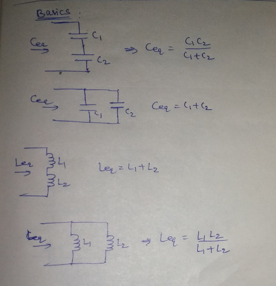
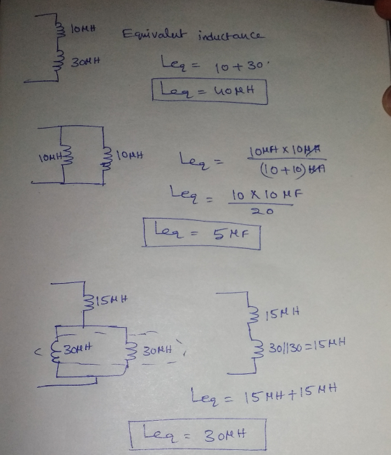
![9 points each blank, 6 points total] Determine the equivalent values of capacitance and inductance at the of the component co](http://img.homeworklib.com/questions/03dfa220-0c18-11ec-a7d0-0db79e4616ac.png?x-oss-process=image/resize,w_560)
Homework Answers

Add Answer to:
9 points each blank, 6 points total] Determine the equivalent values of capacitance and inductance at...
Please explain each step in the solution 6. Find the equivalent capacitance of the combination. Assume...
 Please explain each step in the solution
6. Find the equivalent capacitance of the combination. Assume that Ci is 10 uF, C2 is 5uF and C3 is 4uF (2 marks)
Please explain each step in the solution
6. Find the equivalent capacitance of the combination. Assume that Ci is 10 uF, C2 is 5uF and C3 is 4uF (2 marks)
5. (20 points) Find total inductance Lj and total capacitance CT at terminals a and b...
 5. (20 points) Find total inductance Lj and total capacitance CT at terminals a and b for the circuits below. 25H 18 H 60 H o uH 3 20 uH 3 375 uH 312 uH 15 uH 38 #H .... - - 6 uF 4 uF 6 uF 8 uF C - 5 uF 12 uF 6 uF ਤੇ ਘF 10 uF 6 IF
Determine the equivalent capacitance between points A and B for the capacitors shown in the circuit...
 Determine the equivalent capacitance between points A and B for the capacitors shown in the circuit below. 9) 5.0p F 24μ'F 4.0μ F 12μ F
Group Problem 2: You are given the task to determine the inductance M of two inductors...
 Group Problem 2: You are given the task to determine the inductance M of two inductors of unknown self-inductances L1 and L2. Recall that M = M12 = M21 and the magnetic flux B1,2 = M12/1 and B2,1 = M2112. To perform this task, you connect one of the inductors (say L1) in series with a battery of emf = 10 V and a resistor of resistance R1 = 212. These three components, as well as a switch S, form...
inductance = .1 H Line = 20 Ohm 3. (30 points total) The load from a...
 inductance = .1 H
Line = 20 Ohm
3. (30 points total) The load from a plant is equivalent to a resistor in series with an inductor as shown. The plant is supplied by a source through a long line which has a resistance of 20 ohms as shown in the circuit below. You decide to place a capacitor in parallel with the load so that the reactive power by the source is reduced to zero. (a) What capacitance value...
inductance = .1 H
Line = 20 Ohm
3. (30 points total) The load from a plant is equivalent to a resistor in series with an inductor as shown. The plant is supplied by a source through a long line which has a resistance of 20 ohms as shown in the circuit below. You decide to place a capacitor in parallel with the load so that the reactive power by the source is reduced to zero. (a) What capacitance value...
Construct series and parallel combinations of inductors to yield the equivalent inductance 9 mH. Drag the...
 Construct series and parallel combinations of inductors to yield the equivalent inductance 9 mH. Drag the terms on the left to the appropriate blanks on the right to complete the sentences. Use realistic inductor values from the following table to construct series and parallel combinations of inductors to yield the equivalent inductances specified below. Try to minimize the number of inductors used. Assume that no initial energy is stored in any of the inductors. Inductor values 10 μΗ 100 μΗ...
4. (a) Without using a shortcut, determine the charge on each capacitor and the equivalent capacitance...
 4. (a) Without using a shortcut, determine the charge on each capacitor and the equivalent capacitance of the capacitor circuit shown below. Ci-C4=C,=C,C,=C2-2C. Your answer will depend on C and V. (b) What is the voltage difference between points c and d? Based on your answer, indicate how the plates of capacitor 5 polarize. Cz
(3 points for each blank cell in table, 30 points total) The following diagram shows a...
 (3 points for each blank cell in table, 30 points total) The following diagram shows a circuit of three resistors in series connected to a 9V battery. A voltmeter measures the voltage across R1 and finds that it is 2.62V. Use the resistor color coding chart and Ohm's Law to complete the table below 2. Resistor Colors Resistance (k) Voltage Across (V) Current through (mA) Circuit Element R1 R2 R3 Total 2.62 V reen-black-red-gold red-red-red-gold brown-black-orange-gold 9V 2.62 V R1...
Solve it and show the work for each circuits 11. Determine the total resistance of the...
 Solve it and show the work for each circuits
11. Determine the total resistance of the circuit illustrated to the right using the reciprocal formula introduced in class R1 2.2k03.3k0 R2 15 V 12. Construct the circuit illustrated to the right and, with the source 13. Use the total resistance to calculate the total circuit current. 14. Connect the source to the circuit and measure the total circuit current. 15. Determine the percent deviation of the resistance and current. 16....
Solve it and show the work for each circuits
11. Determine the total resistance of the circuit illustrated to the right using the reciprocal formula introduced in class R1 2.2k03.3k0 R2 15 V 12. Construct the circuit illustrated to the right and, with the source 13. Use the total resistance to calculate the total circuit current. 14. Connect the source to the circuit and measure the total circuit current. 15. Determine the percent deviation of the resistance and current. 16....
Part "c" Please! Consider the circuit below. Assume that the only inductance of interest is the...
 Part "c" Please!
Consider the circuit below. Assume that the only inductance of interest is the load inductor L = 15mH connected to the output terminal. The resistors have the following values: R1 = 5kN, R2 = 2kN, R3 = 0.1kN, and RI, = 10kN. The supply voltage is Vs = 15V. Vs R2 R, vo R1 R3 Figure 6-1 It is known that the input voltage vị can be decomposed into two parts, a constant Vị and a small...
Part "c" Please!
Consider the circuit below. Assume that the only inductance of interest is the load inductor L = 15mH connected to the output terminal. The resistors have the following values: R1 = 5kN, R2 = 2kN, R3 = 0.1kN, and RI, = 10kN. The supply voltage is Vs = 15V. Vs R2 R, vo R1 R3 Figure 6-1 It is known that the input voltage vị can be decomposed into two parts, a constant Vị and a small...
 Please explain each step in the solution
6. Find the equivalent capacitance of the combination. Assume that Ci is 10 uF, C2 is 5uF and C3 is 4uF (2 marks)
Please explain each step in the solution
6. Find the equivalent capacitance of the combination. Assume that Ci is 10 uF, C2 is 5uF and C3 is 4uF (2 marks)
 5. (20 points) Find total inductance Lj and total capacitance CT at terminals a and b for the circuits below. 25H 18 H 60 H o uH 3 20 uH 3 375 uH 312 uH 15 uH 38 #H .... - - 6 uF 4 uF 6 uF 8 uF C - 5 uF 12 uF 6 uF ਤੇ ਘF 10 uF 6 IF
 Determine the equivalent capacitance between points A and B for the capacitors shown in the circuit below. 9) 5.0p F 24μ'F 4.0μ F 12μ F
 Group Problem 2: You are given the task to determine the inductance M of two inductors of unknown self-inductances L1 and L2. Recall that M = M12 = M21 and the magnetic flux B1,2 = M12/1 and B2,1 = M2112. To perform this task, you connect one of the inductors (say L1) in series with a battery of emf = 10 V and a resistor of resistance R1 = 212. These three components, as well as a switch S, form...
 inductance = .1 H
Line = 20 Ohm
3. (30 points total) The load from a plant is equivalent to a resistor in series with an inductor as shown. The plant is supplied by a source through a long line which has a resistance of 20 ohms as shown in the circuit below. You decide to place a capacitor in parallel with the load so that the reactive power by the source is reduced to zero. (a) What capacitance value...
inductance = .1 H
Line = 20 Ohm
3. (30 points total) The load from a plant is equivalent to a resistor in series with an inductor as shown. The plant is supplied by a source through a long line which has a resistance of 20 ohms as shown in the circuit below. You decide to place a capacitor in parallel with the load so that the reactive power by the source is reduced to zero. (a) What capacitance value...
 Construct series and parallel combinations of inductors to yield the equivalent inductance 9 mH. Drag the terms on the left to the appropriate blanks on the right to complete the sentences. Use realistic inductor values from the following table to construct series and parallel combinations of inductors to yield the equivalent inductances specified below. Try to minimize the number of inductors used. Assume that no initial energy is stored in any of the inductors. Inductor values 10 μΗ 100 μΗ...
 4. (a) Without using a shortcut, determine the charge on each capacitor and the equivalent capacitance of the capacitor circuit shown below. Ci-C4=C,=C,C,=C2-2C. Your answer will depend on C and V. (b) What is the voltage difference between points c and d? Based on your answer, indicate how the plates of capacitor 5 polarize. Cz
 (3 points for each blank cell in table, 30 points total) The following diagram shows a circuit of three resistors in series connected to a 9V battery. A voltmeter measures the voltage across R1 and finds that it is 2.62V. Use the resistor color coding chart and Ohm's Law to complete the table below 2. Resistor Colors Resistance (k) Voltage Across (V) Current through (mA) Circuit Element R1 R2 R3 Total 2.62 V reen-black-red-gold red-red-red-gold brown-black-orange-gold 9V 2.62 V R1...
 Solve it and show the work for each circuits
11. Determine the total resistance of the circuit illustrated to the right using the reciprocal formula introduced in class R1 2.2k03.3k0 R2 15 V 12. Construct the circuit illustrated to the right and, with the source 13. Use the total resistance to calculate the total circuit current. 14. Connect the source to the circuit and measure the total circuit current. 15. Determine the percent deviation of the resistance and current. 16....
Solve it and show the work for each circuits
11. Determine the total resistance of the circuit illustrated to the right using the reciprocal formula introduced in class R1 2.2k03.3k0 R2 15 V 12. Construct the circuit illustrated to the right and, with the source 13. Use the total resistance to calculate the total circuit current. 14. Connect the source to the circuit and measure the total circuit current. 15. Determine the percent deviation of the resistance and current. 16....
 Part "c" Please!
Consider the circuit below. Assume that the only inductance of interest is the load inductor L = 15mH connected to the output terminal. The resistors have the following values: R1 = 5kN, R2 = 2kN, R3 = 0.1kN, and RI, = 10kN. The supply voltage is Vs = 15V. Vs R2 R, vo R1 R3 Figure 6-1 It is known that the input voltage vị can be decomposed into two parts, a constant Vị and a small...
Part "c" Please!
Consider the circuit below. Assume that the only inductance of interest is the load inductor L = 15mH connected to the output terminal. The resistors have the following values: R1 = 5kN, R2 = 2kN, R3 = 0.1kN, and RI, = 10kN. The supply voltage is Vs = 15V. Vs R2 R, vo R1 R3 Figure 6-1 It is known that the input voltage vị can be decomposed into two parts, a constant Vị and a small...
Most questions answered within 3 hours.
-
use
hardy wineberg equation to find equilbrium.
AA 150. Aa 120. aa 90
asked 21 seconds ago -
Two children (m = 31.0 kg each) stand opposite each other on the
edge of a...
asked 1 minute ago -
A 2180-kg car is slowed down uniformly from 24.6 m/s to 5.2 m/s
in 3.32 s....
asked 27 minutes ago -
Jesse’s Machining is looking to buy a new machine to handle a
new four-year contract for...
asked 33 minutes ago -
5. A slide mount of a fungal specimen is prepared. A slide and
coverslip are flame-sterilized....
asked 35 minutes ago -
A parallel plate capacitor has a charge Q, plates of area A and
separation d, where...
asked 38 minutes ago -
This question goes along with my test results for a psychology
seminar. The results were the...
asked 38 minutes ago -
A calorimeter contains 35.0 mL of water at 13.0 ∘C . When 1.40 g
of X...
asked 43 minutes ago -
[The following information applies to the questions
displayed below.]
Arndt, Inc. reported the following for 2021...
asked 44 minutes ago -
Equivalent Units of Conversion Costs
The Rolling Department of Kraus Steel Company had 2,370 tons in...
asked 50 minutes ago -
Genetic differences between closely related species are due to
changes at both synonymous and nonsynonymous sites...
asked 56 minutes ago -
Assignment:
Implement an 8 bit register in VHDL/Verilog using Model Sim
software. Show two test cases...
asked 1 hour ago