
Homework Answers
Add Answer to:
A composite rod is made up of typical structural steel (on the inside) and high strength...
4. An Am1004-T61 magnesium tube is bonded to a central A36 steel rod. Sketch and label...
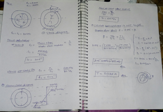
 4. An Am1004-T61 magnesium tube is bonded to a central A36 steel rod. Sketch and label the shear stress distribution across the entire radius of the composite member when a torque of 4.8 kN-m is applied. Sketch the corresponding shear strain distribution. 900 mm 80 mimA 40 mm 80 mm4 40 mm 5. For the composite member of Problem 4, assume that both materials are perfectly plastic once they yield. Furthermore, assume that the shear yield stress of the magnesium...
Rod ABC is made of a steel for which the yield strength is oy= 450 MPa...
 Rod ABC is made of a steel for which the yield strength is oy= 450 MPa and the modulus of elasticity is E-200 GPa. Knowing that a strain energy of 11.2 J must be acquired by the rod as the axial load P is applied, determine the factor of safety of the rod with respect to permanent deformation when a -0.3 m. 18-mm diameter 12-mm diameter The factor of safety of the rod with respect to permanent deformation is
P6.042 The composite shaft shown in the figure consists of two steel pipes that are connected...
 P6.042 The composite shaft shown in the figure consists of two steel pipes that are connected at flange B and securely attached to rigid walls at A and C. Steel pipe (1) has an outside diameter of 173 mm and a wall thickness of 6 mm. Steel pipe (2) has an outside diameter of 101 mm and a wall thickness of 7 mm. Both pipes are 3.4 m long and have a shear modulus of 80 GPa. If a concentrated...
The A992 steel rod is subjected to the loading shown. If the cross-sectional area of the...
 The A992 steel rod is
subjected to the loading shown. If the cross-sectional area of the
rod is 100 mm2. Neglect the size of the couplings at B and C. The
elastic modulus and yield stress of A992 steel is 200 GPa and 345
MPa respectively. Determine the displacement of B and A with
respect to point D. (Preserve 2 significant digits after the
decimal point.)
QUESTION 1 The 1992 steel rod is subjected to the loading shown. If the...
The A992 steel rod is
subjected to the loading shown. If the cross-sectional area of the
rod is 100 mm2. Neglect the size of the couplings at B and C. The
elastic modulus and yield stress of A992 steel is 200 GPa and 345
MPa respectively. Determine the displacement of B and A with
respect to point D. (Preserve 2 significant digits after the
decimal point.)
QUESTION 1 The 1992 steel rod is subjected to the loading shown. If the...
a cylindrical tank is made from A-36 OBLEM 2: The cylindrical tank is made from A-36 steel with a yield strength ayie 250 MPa, modulus ef elasticity &-200 GPa and Poisson's ratio v 0.3. W...
 a cylindrical tank is made from A-36
OBLEM 2: The cylindrical tank is made from A-36 steel with a yield strength ayie 250 MPa, modulus ef elasticity &-200 GPa and Poisson's ratio v 0.3. When the tank is pressuri pressure p, a 60 strain rosette mounted on the surface measures the following strains: & 100(10), 343(10), maximum-distortion-energy theory, to determine the factor of safety against yielding (c) Find the internal pressure p acting within the tank. (30 Points) 343(10) Use...
a cylindrical tank is made from A-36
OBLEM 2: The cylindrical tank is made from A-36 steel with a yield strength ayie 250 MPa, modulus ef elasticity &-200 GPa and Poisson's ratio v 0.3. When the tank is pressuri pressure p, a 60 strain rosette mounted on the surface measures the following strains: & 100(10), 343(10), maximum-distortion-energy theory, to determine the factor of safety against yielding (c) Find the internal pressure p acting within the tank. (30 Points) 343(10) Use...
Figure 2a shows a composite beam made by placing three steel plates inside a wooden section....
 Figure 2a shows a composite beam made by placing three
steel plates inside a wooden
section.
(a) Determine the maximum bending stress developed in the wooden
section and steel plate
if the beam is subjected to allowable bending moment, M of 20 kN.m.
Given that the
Modulus of Elasticity of wood is 13.1 GPa and steel is 200
GPa.
[14 Marks]
Figure 2a: Composite beam
(b) Figure 2b shows another beam without steel plates. Suggest the
maximum bending
stress for...
Figure 2a shows a composite beam made by placing three
steel plates inside a wooden
section.
(a) Determine the maximum bending stress developed in the wooden
section and steel plate
if the beam is subjected to allowable bending moment, M of 20 kN.m.
Given that the
Modulus of Elasticity of wood is 13.1 GPa and steel is 200
GPa.
[14 Marks]
Figure 2a: Composite beam
(b) Figure 2b shows another beam without steel plates. Suggest the
maximum bending
stress for...
Need ASAP, Show all steps. Thanks. Supplemental Problems 10.16 A 12-in.-diameter structural nickel steel specimen was...
 Need ASAP, Show all steps. Thanks.
Supplemental Problems 10.16 A 12-in.-diameter structural nickel steel specimen was subjected to a tension test. After rupture it was determined that the 2-in. standard-gage length had stretched to 2.42 in. The minimum diameter at the fracture was measured to be 0.422 in. Compute the percent elongation and percent reduction in area. 10.20 During a tensile test of a steel specimen, the strain at a stress of 35 MPa was calculated to be 0.000 170...
Need ASAP, Show all steps. Thanks.
Supplemental Problems 10.16 A 12-in.-diameter structural nickel steel specimen was subjected to a tension test. After rupture it was determined that the 2-in. standard-gage length had stretched to 2.42 in. The minimum diameter at the fracture was measured to be 0.422 in. Compute the percent elongation and percent reduction in area. 10.20 During a tensile test of a steel specimen, the strain at a stress of 35 MPa was calculated to be 0.000 170...
Question 5: Draw a typical stress-strain relationship (graph) for steel subjected to tension. On that graph,...
 Question 5: Draw a typical stress-strain relationship (graph) for steel subjected to tension. On that graph, show the initial tangent modulus (slope only), proportional limit, elastic limit, the yield strength, ultimate strength and rupture stress. Also indicate the area that would be used to determine the modulus of resilience. (2+6+3 =11 Points)
160 mm 10 mm A hollow cylindrical steel shaft is 1.5 m long and has inner...
 160 mm 10 mm A hollow cylindrical steel shaft is 1.5 m long and has inner and outer diameters respectively equal to 40 and 60 mm. The allowable shearing stress is 120 MPa with a modulus of rigidity (shear modulus) G-77 GPa, assuming fully elastic deformation. (a) What is the largest torque that can be applied to the shaft? (5 points) (b) What is the corresponding minimum value of the shearing stress in the shaft? (5 points) (c) What are...
Problem 1 A half solid, half shell Steel shaft ABCD is fixed to a rigid wall...
 Problem 1 A half solid, half shell Steel shaft ABCD is fixed to a rigid wall at its end A and has the dimensions shown in the figure below. Torques Ti and T2 are applied at sections B and D in the indicated directions, respectively. A solid concentric copper shaft is incased in the shell part of the steel shaft between the rigid wall at end A and the solid portion of the steel shaft at C. Shear modulus of...
 4. An Am1004-T61 magnesium tube is bonded to a central A36 steel rod. Sketch and label the shear stress distribution across the entire radius of the composite member when a torque of 4.8 kN-m is applied. Sketch the corresponding shear strain distribution. 900 mm 80 mimA 40 mm 80 mm4 40 mm 5. For the composite member of Problem 4, assume that both materials are perfectly plastic once they yield. Furthermore, assume that the shear yield stress of the magnesium...
 Rod ABC is made of a steel for which the yield strength is oy= 450 MPa and the modulus of elasticity is E-200 GPa. Knowing that a strain energy of 11.2 J must be acquired by the rod as the axial load P is applied, determine the factor of safety of the rod with respect to permanent deformation when a -0.3 m. 18-mm diameter 12-mm diameter The factor of safety of the rod with respect to permanent deformation is
 P6.042 The composite shaft shown in the figure consists of two steel pipes that are connected at flange B and securely attached to rigid walls at A and C. Steel pipe (1) has an outside diameter of 173 mm and a wall thickness of 6 mm. Steel pipe (2) has an outside diameter of 101 mm and a wall thickness of 7 mm. Both pipes are 3.4 m long and have a shear modulus of 80 GPa. If a concentrated...
 The A992 steel rod is
subjected to the loading shown. If the cross-sectional area of the
rod is 100 mm2. Neglect the size of the couplings at B and C. The
elastic modulus and yield stress of A992 steel is 200 GPa and 345
MPa respectively. Determine the displacement of B and A with
respect to point D. (Preserve 2 significant digits after the
decimal point.)
QUESTION 1 The 1992 steel rod is subjected to the loading shown. If the...
The A992 steel rod is
subjected to the loading shown. If the cross-sectional area of the
rod is 100 mm2. Neglect the size of the couplings at B and C. The
elastic modulus and yield stress of A992 steel is 200 GPa and 345
MPa respectively. Determine the displacement of B and A with
respect to point D. (Preserve 2 significant digits after the
decimal point.)
QUESTION 1 The 1992 steel rod is subjected to the loading shown. If the...
 a cylindrical tank is made from A-36
OBLEM 2: The cylindrical tank is made from A-36 steel with a yield strength ayie 250 MPa, modulus ef elasticity &-200 GPa and Poisson's ratio v 0.3. When the tank is pressuri pressure p, a 60 strain rosette mounted on the surface measures the following strains: & 100(10), 343(10), maximum-distortion-energy theory, to determine the factor of safety against yielding (c) Find the internal pressure p acting within the tank. (30 Points) 343(10) Use...
a cylindrical tank is made from A-36
OBLEM 2: The cylindrical tank is made from A-36 steel with a yield strength ayie 250 MPa, modulus ef elasticity &-200 GPa and Poisson's ratio v 0.3. When the tank is pressuri pressure p, a 60 strain rosette mounted on the surface measures the following strains: & 100(10), 343(10), maximum-distortion-energy theory, to determine the factor of safety against yielding (c) Find the internal pressure p acting within the tank. (30 Points) 343(10) Use...
 Figure 2a shows a composite beam made by placing three
steel plates inside a wooden
section.
(a) Determine the maximum bending stress developed in the wooden
section and steel plate
if the beam is subjected to allowable bending moment, M of 20 kN.m.
Given that the
Modulus of Elasticity of wood is 13.1 GPa and steel is 200
GPa.
[14 Marks]
Figure 2a: Composite beam
(b) Figure 2b shows another beam without steel plates. Suggest the
maximum bending
stress for...
Figure 2a shows a composite beam made by placing three
steel plates inside a wooden
section.
(a) Determine the maximum bending stress developed in the wooden
section and steel plate
if the beam is subjected to allowable bending moment, M of 20 kN.m.
Given that the
Modulus of Elasticity of wood is 13.1 GPa and steel is 200
GPa.
[14 Marks]
Figure 2a: Composite beam
(b) Figure 2b shows another beam without steel plates. Suggest the
maximum bending
stress for...
 Need ASAP, Show all steps. Thanks.
Supplemental Problems 10.16 A 12-in.-diameter structural nickel steel specimen was subjected to a tension test. After rupture it was determined that the 2-in. standard-gage length had stretched to 2.42 in. The minimum diameter at the fracture was measured to be 0.422 in. Compute the percent elongation and percent reduction in area. 10.20 During a tensile test of a steel specimen, the strain at a stress of 35 MPa was calculated to be 0.000 170...
Need ASAP, Show all steps. Thanks.
Supplemental Problems 10.16 A 12-in.-diameter structural nickel steel specimen was subjected to a tension test. After rupture it was determined that the 2-in. standard-gage length had stretched to 2.42 in. The minimum diameter at the fracture was measured to be 0.422 in. Compute the percent elongation and percent reduction in area. 10.20 During a tensile test of a steel specimen, the strain at a stress of 35 MPa was calculated to be 0.000 170...
 Question 5: Draw a typical stress-strain relationship (graph) for steel subjected to tension. On that graph, show the initial tangent modulus (slope only), proportional limit, elastic limit, the yield strength, ultimate strength and rupture stress. Also indicate the area that would be used to determine the modulus of resilience. (2+6+3 =11 Points)
 160 mm 10 mm A hollow cylindrical steel shaft is 1.5 m long and has inner and outer diameters respectively equal to 40 and 60 mm. The allowable shearing stress is 120 MPa with a modulus of rigidity (shear modulus) G-77 GPa, assuming fully elastic deformation. (a) What is the largest torque that can be applied to the shaft? (5 points) (b) What is the corresponding minimum value of the shearing stress in the shaft? (5 points) (c) What are...
 Problem 1 A half solid, half shell Steel shaft ABCD is fixed to a rigid wall at its end A and has the dimensions shown in the figure below. Torques Ti and T2 are applied at sections B and D in the indicated directions, respectively. A solid concentric copper shaft is incased in the shell part of the steel shaft between the rigid wall at end A and the solid portion of the steel shaft at C. Shear modulus of...
Most questions answered within 3 hours.
-
A sine wave signal is displayed on the screen of an
oscilloscope. 6 peak-to-peak divisions are...
asked 2 hours ago -
a
1500 kg car accelerates from 0 to 25 m / s in 21.0s. How much...
asked 3 hours ago -
Calculate the molarity of each of the following solutions:
(a) 30.5 g of ethanol (C2H5OH) in...
asked 3 hours ago -
1 Refer to the build-borrow-or-buy framework as a decision tree
for the Adidas company. Identify a...
asked 3 hours ago -
Problem 2: The Problem of Social Cost. A Rancher and Farmer live
side-by-side to each other....
asked 4 hours ago -
a uniform bar of weight 40N is 4 meter long. weights
on 60N and 100N are...
asked 4 hours ago -
Define Diet counceling? What are the
responsibilities of a counselor?
asked 6 hours ago -
Hey im just confused about how to put the ' A angle n' and ' S...
asked 6 hours ago -
A short essay about the WSJ article on Oreo versus Hydrox.
asked 6 hours ago -
##8. A program contains the following function definition:
##def cube(num):
##return num * num * num...
asked 6 hours ago -
find the value z of a standard Normal variable that satisfies
each of the given conditions....
asked 7 hours ago -
"banana".find('z')
Out[22]: -1
why is this -1
python 3.7
asked 6 hours ago