

Homework Answers


Add Answer to:
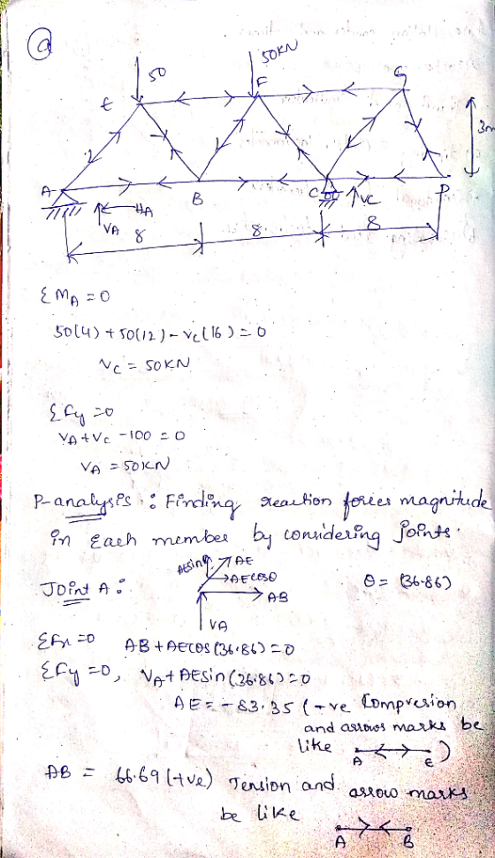
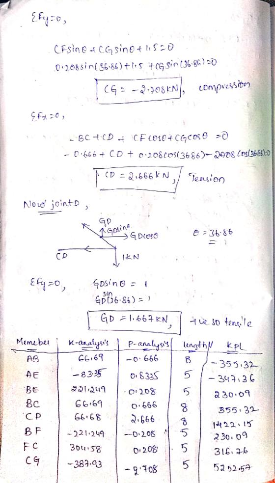
Question 1 (a) The truss of Figure 1 is subject to point loads at E and...
Question Four: For the pin-jointed truss shown in Figure 4, 3m 12 KN 3m 30 kN 3m 15 kN 4m 4m 3m 3m 6m Figure 4. Calcula...
 Question Four: For the pin-jointed truss shown in Figure 4, 3m 12 KN 3m 30 kN 3m 15 kN 4m 4m 3m 3m 6m Figure 4. Calculate the reactions at A and B. (a) By inspection (involving no calculations), list all the zero force members. (b) (c) By method of joints, analyse joints T, S and N to determine the force in members ST NT, RS, SN, MN and RN. In your answer, you must state whether the members are...
The following truss is subjected to vertical loads of 20 KN at joints E and D....
 The following truss is subjected to vertical loads of 20 KN at
joints E and D. In addition to the loads, support A settles by 5 mm
and member AB and BC are subjected to a temperature drop of 50°C.
Given Young’s modulus, E = 200 GPa, cross sectional area for each
member, A = 500 mm2 and coefficient of thermal expansion
of, α = 1.25 x 10⁻⁵/°C.
Find the internal forces in each member using force
method.
20 KN...
The following truss is subjected to vertical loads of 20 KN at
joints E and D. In addition to the loads, support A settles by 5 mm
and member AB and BC are subjected to a temperature drop of 50°C.
Given Young’s modulus, E = 200 GPa, cross sectional area for each
member, A = 500 mm2 and coefficient of thermal expansion
of, α = 1.25 x 10⁻⁵/°C.
Find the internal forces in each member using force
method.
20 KN...
8.4-8. Conside r a statically indeterminate elasti ic beam which is subject to two concentrated loads,...
 8.4-8. Conside r a statically indeterminate elasti ic beam which is subject to two concentrated loads, each of magnitude F', as in the figure. Im (a) Write a mathematical expression for the applied loads using singu larity functions (b) Write the boundarv conditions that apply to the two end-points A and B of the beam (c) Use the results of part (a) and (b) to determine the deflection v of the beam as a function of x (d) Locate the...
3) Statically Indeterminate Truss (15 pts). For the truss shown below all the members have elastic modulus E, normal failure stress σ, shear failure stress τ, and cross-sectional area A. All answers...
 3) Statically Indeterminate Truss (15 pts). For the truss shown below all the members have elastic modulus E, normal failure stress σ, shear failure stress τ, and cross-sectional area A. All answers should be given in terms of P, W, A, E, σ, and/orT5 (a - 10 pts) Solve for the reaction forces at points B and D and the magnitude of the deflection of point C (b - 5 pts) Given a safety factor of 1.5, write an expression...
2. For the pin-jointed truss shown in Figure Q2.1 applied at node 4. The Young's modulus E(GPa) is the same for...
 2. For the pin-jointed truss shown in Figure Q2.1 applied at node 4. The Young's modulus E(GPa) is the same for the three truss vertical downward force P(kN) is a members. The cross sectional area of each of the truss members is indicated below and expressed in terms of a constant A. By using the stiffness method: (a) Compute the reduced stiffness matrix Kg [5 marks [10 marks (b) Calculate the global displacements of node 4 in terms of P,...
Weyheit & Figure 2: Loading Case 1 ORT Figure 3: Loading Case 2 499 3 x...
 Weyheit & Figure 2: Loading Case 1 ORT Figure 3: Loading Case 2 499 3 x L Lx L=259 mm 1 2. K L Case # 1 - upward Force at [F] of 191N ↑ Forces in members: 1=226N, 2 = 171N, 3= ON, U=ON, 5=UN, 6=-250N, 7=99N, 8 = -4N, 9 =-113N, 10 = -203N Case #2 - downward Force at [Fa] of 170NI Forces in members : 1 = -298N, 2 = -295N, 3 = -295N, 4 =...
please answer question 2a and 2b with clear steps and remarks (a) For the pin-jointed truss...
 please answer question 2a and 2b with clear steps and
remarks
(a) For the pin-jointed truss under design loads shown in Figure 2(a), member BC, AC and AD using the Method of Sections. Indicate whether the members are in tension (T) or compression (C) calculate the forces in 20 kN 70 kN 45° 45° 45° 45 80 kN 45° 45 4m 4m 4m L 4m 4m Figure 2(a) (b) A sample of a steel member was taken for tensile testing...
please answer question 2a and 2b with clear steps and
remarks
(a) For the pin-jointed truss under design loads shown in Figure 2(a), member BC, AC and AD using the Method of Sections. Indicate whether the members are in tension (T) or compression (C) calculate the forces in 20 kN 70 kN 45° 45° 45° 45 80 kN 45° 45 4m 4m 4m L 4m 4m Figure 2(a) (b) A sample of a steel member was taken for tensile testing...
Question 1 (25%) For the truss shown on figure 1, determine the horizontal displacement of point...
 Question 1 (25%) For the truss shown on figure 1, determine the horizontal displacement of point C when P 1000 N and P2 -0. Also, determine the vertical displacement of point F when P 0 et P2 1000 N. All members are prismatic and have the same elastic modulus fixed at 200 GPa. Area of each member is indicated in brackets (mm2). A (4000)B(400C (3000 (3000 2,75 D(5000 E(5000) Pi Figure 1
(a) Warren truss (b) Howe truss (c) Pratt truss (d) Baltimore truss (e) Parker truss Figure...
 (a) Warren truss (b) Howe truss (c) Pratt truss (d) Baltimore truss (e) Parker truss Figure 2: Truss Types (Nielson Text) The truss bridge has the following properties/characteristics: 1. Span length (bottom chord): 168 ft 2. 14 panels (12 ft length per panel) 3. All diagonals are 45 degrees 4. Simple truss (all members are pin-connected and loads are only applied at the joints) 5. Simply-supported (pin at one end, roller at the other) 6. 13 ft width between trusses...
Figure 1 shows a beam is supported by a pin at A and a roller at C. The beam is subjected to point loads 30 kN and 60 kN and a uniformly distributed load of 24 kN/m. Modulus of elasticity, E and momen...
 Figure 1 shows a beam is supported by a pin at A and a roller at
C. The beam is subjected to point
loads 30 kN and 60 kN and a uniformly distributed load of 24 kN/m.
Modulus of elasticity, E and
moment of inertia, I for all members are 205 kN/mm2 and 195 x 106
mm4, respectively. By using
Virtual Work method,
(a) determine the slope at B. (1.801 mrad)
(b) determine the deflection at B and D. (2.4...
Figure 1 shows a beam is supported by a pin at A and a roller at
C. The beam is subjected to point
loads 30 kN and 60 kN and a uniformly distributed load of 24 kN/m.
Modulus of elasticity, E and
moment of inertia, I for all members are 205 kN/mm2 and 195 x 106
mm4, respectively. By using
Virtual Work method,
(a) determine the slope at B. (1.801 mrad)
(b) determine the deflection at B and D. (2.4...
 Question Four: For the pin-jointed truss shown in Figure 4, 3m 12 KN 3m 30 kN 3m 15 kN 4m 4m 3m 3m 6m Figure 4. Calculate the reactions at A and B. (a) By inspection (involving no calculations), list all the zero force members. (b) (c) By method of joints, analyse joints T, S and N to determine the force in members ST NT, RS, SN, MN and RN. In your answer, you must state whether the members are...
 The following truss is subjected to vertical loads of 20 KN at
joints E and D. In addition to the loads, support A settles by 5 mm
and member AB and BC are subjected to a temperature drop of 50°C.
Given Young’s modulus, E = 200 GPa, cross sectional area for each
member, A = 500 mm2 and coefficient of thermal expansion
of, α = 1.25 x 10⁻⁵/°C.
Find the internal forces in each member using force
method.
20 KN...
The following truss is subjected to vertical loads of 20 KN at
joints E and D. In addition to the loads, support A settles by 5 mm
and member AB and BC are subjected to a temperature drop of 50°C.
Given Young’s modulus, E = 200 GPa, cross sectional area for each
member, A = 500 mm2 and coefficient of thermal expansion
of, α = 1.25 x 10⁻⁵/°C.
Find the internal forces in each member using force
method.
20 KN...
 8.4-8. Conside r a statically indeterminate elasti ic beam which is subject to two concentrated loads, each of magnitude F', as in the figure. Im (a) Write a mathematical expression for the applied loads using singu larity functions (b) Write the boundarv conditions that apply to the two end-points A and B of the beam (c) Use the results of part (a) and (b) to determine the deflection v of the beam as a function of x (d) Locate the...
 3) Statically Indeterminate Truss (15 pts). For the truss shown below all the members have elastic modulus E, normal failure stress σ, shear failure stress τ, and cross-sectional area A. All answers should be given in terms of P, W, A, E, σ, and/orT5 (a - 10 pts) Solve for the reaction forces at points B and D and the magnitude of the deflection of point C (b - 5 pts) Given a safety factor of 1.5, write an expression...
 2. For the pin-jointed truss shown in Figure Q2.1 applied at node 4. The Young's modulus E(GPa) is the same for the three truss vertical downward force P(kN) is a members. The cross sectional area of each of the truss members is indicated below and expressed in terms of a constant A. By using the stiffness method: (a) Compute the reduced stiffness matrix Kg [5 marks [10 marks (b) Calculate the global displacements of node 4 in terms of P,...
 Weyheit & Figure 2: Loading Case 1 ORT Figure 3: Loading Case 2 499 3 x L Lx L=259 mm 1 2. K L Case # 1 - upward Force at [F] of 191N ↑ Forces in members: 1=226N, 2 = 171N, 3= ON, U=ON, 5=UN, 6=-250N, 7=99N, 8 = -4N, 9 =-113N, 10 = -203N Case #2 - downward Force at [Fa] of 170NI Forces in members : 1 = -298N, 2 = -295N, 3 = -295N, 4 =...
 please answer question 2a and 2b with clear steps and
remarks
(a) For the pin-jointed truss under design loads shown in Figure 2(a), member BC, AC and AD using the Method of Sections. Indicate whether the members are in tension (T) or compression (C) calculate the forces in 20 kN 70 kN 45° 45° 45° 45 80 kN 45° 45 4m 4m 4m L 4m 4m Figure 2(a) (b) A sample of a steel member was taken for tensile testing...
please answer question 2a and 2b with clear steps and
remarks
(a) For the pin-jointed truss under design loads shown in Figure 2(a), member BC, AC and AD using the Method of Sections. Indicate whether the members are in tension (T) or compression (C) calculate the forces in 20 kN 70 kN 45° 45° 45° 45 80 kN 45° 45 4m 4m 4m L 4m 4m Figure 2(a) (b) A sample of a steel member was taken for tensile testing...
 Question 1 (25%) For the truss shown on figure 1, determine the horizontal displacement of point C when P 1000 N and P2 -0. Also, determine the vertical displacement of point F when P 0 et P2 1000 N. All members are prismatic and have the same elastic modulus fixed at 200 GPa. Area of each member is indicated in brackets (mm2). A (4000)B(400C (3000 (3000 2,75 D(5000 E(5000) Pi Figure 1
 (a) Warren truss (b) Howe truss (c) Pratt truss (d) Baltimore truss (e) Parker truss Figure 2: Truss Types (Nielson Text) The truss bridge has the following properties/characteristics: 1. Span length (bottom chord): 168 ft 2. 14 panels (12 ft length per panel) 3. All diagonals are 45 degrees 4. Simple truss (all members are pin-connected and loads are only applied at the joints) 5. Simply-supported (pin at one end, roller at the other) 6. 13 ft width between trusses...
 Figure 1 shows a beam is supported by a pin at A and a roller at
C. The beam is subjected to point
loads 30 kN and 60 kN and a uniformly distributed load of 24 kN/m.
Modulus of elasticity, E and
moment of inertia, I for all members are 205 kN/mm2 and 195 x 106
mm4, respectively. By using
Virtual Work method,
(a) determine the slope at B. (1.801 mrad)
(b) determine the deflection at B and D. (2.4...
Figure 1 shows a beam is supported by a pin at A and a roller at
C. The beam is subjected to point
loads 30 kN and 60 kN and a uniformly distributed load of 24 kN/m.
Modulus of elasticity, E and
moment of inertia, I for all members are 205 kN/mm2 and 195 x 106
mm4, respectively. By using
Virtual Work method,
(a) determine the slope at B. (1.801 mrad)
(b) determine the deflection at B and D. (2.4...
Most questions answered within 3 hours.
-
The average length of time between arrivals at a turnpike
toll-booth is 26 seconds. What is...
asked 1 hour ago -
(a) A piston at 6.1 atm contains a gas that occupies a volume of
3.5 L....
asked 2 hours ago -
Please answer true or false. Words
cannot be changed or added in to make it true...
asked 2 hours ago -
An empty test tube weighs 15.923 grams. Then,
MgCl2•6H2O is added into the test tube. After...
asked 2 hours ago -
Assume memory access is 10 units of time and disk access is
10000 units of time....
asked 2 hours ago -
1. Are all good samples random?
2. Magazines often report surveys giving statistics such as “63%...
asked 2 hours ago -
Under all the various types of market structures, firms
must eventually earn some economic profits for...
asked 2 hours ago -
Consider the following fitness regime for a single locus trait
with two co-dominant alleles: w11 =...
asked 2 hours ago -
A large cable company reports the following.
80% of its customers subscribe to its cable TV...
asked 3 hours ago -
Please answer the question in brief.
Discuss the role of ERP in organizations. Are ERP tools...
asked 2 hours ago -
Discuss the pros and cons of collaborative software such
as SameTime. Does it increase productivity? What...
asked 2 hours ago -
Buying your in-laws a gift because it’s expected is
due to the ____________ motive of gift-giving....
asked 3 hours ago