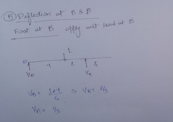
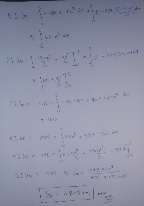
Figure 1 shows a beam is supported by a pin at A and a roller at
C. The beam is subjected to point
loads 30 kN and 60 kN and a uniformly distributed load of 24 kN/m.
Modulus of elasticity, E and
moment of inertia, I for all members are 205 kN/mm2 and 195 x 106
mm4, respectively. By using
Virtual Work method,
(a) determine the slope at B. (1.801 mrad)
(b) determine the deflection at B and D. (2.4 mm, 5.2 mm)

Homework Answers


Add Answer to:
Figure 1 shows a beam is supported by a pin at A and a roller at C. The beam is subjected to point loads 30 kN and 60 kN and a uniformly distributed load of 24 kN/m. Modulus of elasticity, E and momen...
a w310 x 129 I-beam, made of a36 steel, is shown in the figure. this I-beam is 4 m long and has a distributed load and a concentrated load as shown in the figure. determine the slope at point b and de...
 a w310 x 129 I-beam, made of
a36 steel, is shown in the figure. this I-beam is 4 m long and has
a distributed load and a concentrated load as shown in the figure.
determine the slope at point b and deflection at point c. the
modulus of elasticity of A-36 steel is E = 200GPA. the answers
should contain no variables
15 kN/m 20 kN 2 m im Wide-Flange Sections or W Shapes SI Units Flange Web x-x axis...
a w310 x 129 I-beam, made of
a36 steel, is shown in the figure. this I-beam is 4 m long and has
a distributed load and a concentrated load as shown in the figure.
determine the slope at point b and deflection at point c. the
modulus of elasticity of A-36 steel is E = 200GPA. the answers
should contain no variables
15 kN/m 20 kN 2 m im Wide-Flange Sections or W Shapes SI Units Flange Web x-x axis...
A simply supported reinforced concrete beam of 8 m span is subjected to uniformly distributed load...
 A simply supported reinforced concrete beam of 8 m span is subjected to uniformly distributed load as shown in Figure 3. The following data are given: The ultimate load, wu is 60 kN/m; characteristic strength of concrete, fck is 30 N/mm²; characteristic strength of reinforcement, fyk is 500 N/mm2. The effective depth, d is 650 mm. Take the link diameter, w as 10 mm, main bar diameter, o as 20 mm and concrete cover as 30 mm. Design the shear...
Q2 The 10 m long simply supported beam is subjected to a uniformly distributed load w...
 Q2 The 10 m long simply supported beam is subjected to a uniformly distributed load w = 10 kN/m throughout and a point load P =10 kN at the midspan of the beam, as shown in Figure Q2 (a). The cross section of this beam is depicted in Figure Q2 (b), which consists of three equal rectangular steel members. Self-weight of the beam is neglected. 30 mm P= 10 KN W = 10 kN/m 200 mm 5 m 5 m...
Q2 The 10 m long simply supported beam is subjected to a uniformly distributed load w...
 Q2 The 10 m long simply supported beam is subjected to a uniformly distributed load w = 10 kN/m throughout and a point load P =10 kN at the midspan of the beam, as shown in Figure Q2 (a). The cross section of this beam is depicted in Figure Q2 (b), which consists of three equal rectangular steel members. Self-weight of the beam is neglected. 30 mm P = 10 kN W = 10 kN/m 200 mm 5 m 5...
Q2 The 10 m long simply supported beam is subjected to a uniformly distributed load w...
 Q2 The 10 m long simply supported beam is subjected to a uniformly distributed load w = 10 kN/m throughout and a point load P =10 kN at the midspan of the beam, as shown in Figure Q2 (a). The cross section of this beam is depicted in Figure Q2 (b), which consists of three equal rectangular steel members. Self-weight of the beam is neglected. 30 mm P = 10 kN w = 10 kN/m 200 mm 5 m 5...
A pin-connected beam AC shown in Figure is supported by 1.6m of strut BD. The beam is subjected t...
 A pin-connected beam AC shown in Figure is supported by 1.6m of strut BD. The beam is subjected to uniformly distributed load of 20 kN/m at 2.5m from A and an inclined concentrated load of 30 KN with 30℃ angle at respectively. The beam has a constant cross-sectional area of Abm = 0.004 m2 and the strut has a constant cross sectional area of Ast = 0.002 m2 respectively. The diameter of all pins is 20 mm. I. Determine the resultant...
Question 2 Simply supported beam ABC is subject to a point load and the patch loads...
 Question 2 Simply supported beam ABC is subject to a point load and the patch loads as indicated in Figure Q2. Assume the beam has a uniform cross-section size. The Modulus of Elasticity E = 210x106 kN/m2, second moment of area l=5x10⁵ m. Determine the deflection of beam ABC at the middle point using MacCaulay's Method. Total (15) marks. -30 KN -6 kN/m -3 kN/m B 3 m 4 m * Figure Q2: Simply supported beam ABC
The simply supported beam shown in Figure 1 is pin-supported at A and roller-supported at D....
 The simply supported beam shown in Figure 1 is pin-supported at A and roller-supported at D. la) Replace the distributed loads in Figure 1 by an equivalent resultant force and locate its location with respect to A. {2 + 3 marks 1b) Calculate the reactions at supports A and D. {2 marks 1c) Calculate the shear force and bending moment at point C. {4 marks) 15 kN/m 6 kN/m D B q 3.0 m 3.0 m 3.0 m Figure 1
The figure shows the beam structure supporting distributed load 30 kN/m An d the figure below...
 The figure shows the beam structure supporting distributed load 30 kN/m An d the figure below shows the correct free body diagram of the entire beam structure and the reactions 120 kN 60 kN 60 kN 4 m When using the method of sections to find the internal loads at C, which of the following FBDs is correct? FBD 2 FBD 1 30 kN/m 60 kN 4 m 60 kN FBD 3 120 N FBD 4 120 kN 60 kN...
The simply supported beam is subjected to a uniform distributed load, w of 30 kN/m in...
 The simply supported beam is subjected to a uniform distributed load, w of 30 kN/m in the negative y-direction and a point load, P of 15 kN in the negative z-direction. The total length, L of the beam is 6 m. Answer the questions that follow: 'n Eenvoudige opgelegde balk word belas met 'n uniform verspreide belasting van w 30 kN/m in die negatiewe y-rigting en 'n puntlas P = 15 kN in die negatiewe z-rigting. Die totale lengte, L...
 a w310 x 129 I-beam, made of
a36 steel, is shown in the figure. this I-beam is 4 m long and has
a distributed load and a concentrated load as shown in the figure.
determine the slope at point b and deflection at point c. the
modulus of elasticity of A-36 steel is E = 200GPA. the answers
should contain no variables
15 kN/m 20 kN 2 m im Wide-Flange Sections or W Shapes SI Units Flange Web x-x axis...
a w310 x 129 I-beam, made of
a36 steel, is shown in the figure. this I-beam is 4 m long and has
a distributed load and a concentrated load as shown in the figure.
determine the slope at point b and deflection at point c. the
modulus of elasticity of A-36 steel is E = 200GPA. the answers
should contain no variables
15 kN/m 20 kN 2 m im Wide-Flange Sections or W Shapes SI Units Flange Web x-x axis...
 A simply supported reinforced concrete beam of 8 m span is subjected to uniformly distributed load as shown in Figure 3. The following data are given: The ultimate load, wu is 60 kN/m; characteristic strength of concrete, fck is 30 N/mm²; characteristic strength of reinforcement, fyk is 500 N/mm2. The effective depth, d is 650 mm. Take the link diameter, w as 10 mm, main bar diameter, o as 20 mm and concrete cover as 30 mm. Design the shear...
 Q2 The 10 m long simply supported beam is subjected to a uniformly distributed load w = 10 kN/m throughout and a point load P =10 kN at the midspan of the beam, as shown in Figure Q2 (a). The cross section of this beam is depicted in Figure Q2 (b), which consists of three equal rectangular steel members. Self-weight of the beam is neglected. 30 mm P= 10 KN W = 10 kN/m 200 mm 5 m 5 m...
 Q2 The 10 m long simply supported beam is subjected to a uniformly distributed load w = 10 kN/m throughout and a point load P =10 kN at the midspan of the beam, as shown in Figure Q2 (a). The cross section of this beam is depicted in Figure Q2 (b), which consists of three equal rectangular steel members. Self-weight of the beam is neglected. 30 mm P = 10 kN W = 10 kN/m 200 mm 5 m 5...
 Q2 The 10 m long simply supported beam is subjected to a uniformly distributed load w = 10 kN/m throughout and a point load P =10 kN at the midspan of the beam, as shown in Figure Q2 (a). The cross section of this beam is depicted in Figure Q2 (b), which consists of three equal rectangular steel members. Self-weight of the beam is neglected. 30 mm P = 10 kN w = 10 kN/m 200 mm 5 m 5...
 Question 2 Simply supported beam ABC is subject to a point load and the patch loads as indicated in Figure Q2. Assume the beam has a uniform cross-section size. The Modulus of Elasticity E = 210x106 kN/m2, second moment of area l=5x10⁵ m. Determine the deflection of beam ABC at the middle point using MacCaulay's Method. Total (15) marks. -30 KN -6 kN/m -3 kN/m B 3 m 4 m * Figure Q2: Simply supported beam ABC
 The simply supported beam shown in Figure 1 is pin-supported at A and roller-supported at D. la) Replace the distributed loads in Figure 1 by an equivalent resultant force and locate its location with respect to A. {2 + 3 marks 1b) Calculate the reactions at supports A and D. {2 marks 1c) Calculate the shear force and bending moment at point C. {4 marks) 15 kN/m 6 kN/m D B q 3.0 m 3.0 m 3.0 m Figure 1
 The figure shows the beam structure supporting distributed load 30 kN/m An d the figure below shows the correct free body diagram of the entire beam structure and the reactions 120 kN 60 kN 60 kN 4 m When using the method of sections to find the internal loads at C, which of the following FBDs is correct? FBD 2 FBD 1 30 kN/m 60 kN 4 m 60 kN FBD 3 120 N FBD 4 120 kN 60 kN...
 The simply supported beam is subjected to a uniform distributed load, w of 30 kN/m in the negative y-direction and a point load, P of 15 kN in the negative z-direction. The total length, L of the beam is 6 m. Answer the questions that follow: 'n Eenvoudige opgelegde balk word belas met 'n uniform verspreide belasting van w 30 kN/m in die negatiewe y-rigting en 'n puntlas P = 15 kN in die negatiewe z-rigting. Die totale lengte, L...
Most questions answered within 3 hours.
-
A
752 mL sample of water was placed in a 1000 gram pan of aluminum.
The...
asked 10 seconds from now -
1 point) Given the significance level α=0.01 find the following:
(a) left-tailed z value z= (b)...
asked 1 minute ago -
Calculate the expected value, the variance, and the standard
deviation of the given random variable X....
asked 2 minutes ago -
Assume that in a hydrogen atom, the electron circles the nucleus
in a circle of radius...
asked 6 minutes ago -
Describe two obstacles that makes fixing atmospheric nitrogen
difficult.
asked 11 minutes ago -
T
F 53) Most differences
between human groups are the result of biology rather than
culture....
asked 16 minutes ago -
A 5.20 mW helium neon laser emits a visible laser beam with a
wavelength of 633...
asked 19 minutes ago -
Assignment:
Your
organization has made a strategic decision
to
outsourcework
currently performed in house. You have...
asked 18 minutes ago -
A hospital performs 100 surgeries per week. The probability that
complications after surgery occur is 10%....
asked 18 minutes ago -
In preparing its cash flow statement for the year ended December
31, 2018, Green Co. gathered...
asked 20 minutes ago -
Donna is 18 years old and full time accounting student.She is
saving for an overseas holiday...
asked 21 minutes ago -
Service-oriented architectures (SOA) provide
object-oriented architectures for web platforms that represent a
collection of services. SOA...
asked 21 minutes ago