please answer all thanks very much!
Homework Answers


Note: According to the HomeworkLib guidelines I have posted only one question solution here, next question doesn't depend on this . Kindly post rest of the question in separate post. I did this question in detail with proper explanation . Kindly upvote my answer
Add Answer to:
please answer all thanks very much!
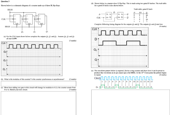
Question 3 Shown below is a schematic diagram of a...
a) (5 marks) Explain the difference between a latch, a gated latch and a flip flop....
 a) (5 marks) Explain the difference between a latch, a gated latch and a flip flop. b) (5 marks) A gated SR latch has the following schematic diagram CLK a) Draw a timing diagram showing the Q and Q outputs for the following sequence of inputs: CLK R Assume that the initial state of the outputs is Q 0 and Q 1 c) (5 marks) Draw a schematic diagram for a rising edge-triggered master-slave D flip- flop built using two...
The following Flip Flops JK fix implements a binary counter; assuming that at time t1, all...
 The following Flip Flops JK fix implements a binary counter;
assuming that at time t1, all outputs Q are ZERO, it indicates the
value of Q2, Q1 and Q0 at time t4.
Q2 = LOW . . Q1 = HIGH . QO = LOW 1 J Q2 J Q1 J QO CLK CLK CLK к Q2 K Q K Q. *All PRE and CLR are HIGH t1 Input clock pulses Talk t1 t2 2 +3 3 14 4 5 6...
The following Flip Flops JK fix implements a binary counter;
assuming that at time t1, all outputs Q are ZERO, it indicates the
value of Q2, Q1 and Q0 at time t4.
Q2 = LOW . . Q1 = HIGH . QO = LOW 1 J Q2 J Q1 J QO CLK CLK CLK к Q2 K Q K Q. *All PRE and CLR are HIGH t1 Input clock pulses Talk t1 t2 2 +3 3 14 4 5 6...
can anyone slove this.Thank you. PROBLEM 2: In the circuit shown, A is a D-type latch...
 can anyone slove this.Thank you.
PROBLEM 2: In the circuit shown, A is a D-type latch and B is a D-type flip flop. For the input waveforms given for the clock signal (Clk) and the input X, accurately draw the resulting waveforms at outputs QA and QB Assume that both Q and Quare initially at 0. X D QH A CIK 22 Clk х D Q B QA DC Qв Draw QA and QB or scan and paste your hand...
can anyone slove this.Thank you.
PROBLEM 2: In the circuit shown, A is a D-type latch and B is a D-type flip flop. For the input waveforms given for the clock signal (Clk) and the input X, accurately draw the resulting waveforms at outputs QA and QB Assume that both Q and Quare initially at 0. X D QH A CIK 22 Clk х D Q B QA DC Qв Draw QA and QB or scan and paste your hand...
3. A timing diagram below shows a D Flip-flop and the input clock. Show the transition...
 3. A timing diagram below shows a D Flip-flop and the input clock. Show the transition of the output Q at the positive transitions of the clock signal. Q 1 initially. Clk 4. Implement a 2-bit up-counter using D flip-flops. Show the circuit. 5. Implement a 2-bit down-counter using D flip-flops. Show the circuit. Transitions: 11->10->01->00->11->10->...
The following is an equivalent way of creating the circuit above. Below is the truth table...
 The following is an equivalent way of creating the circuit
above.
Below is the truth table
Q2, Q1, and Q0 are LED outputs from left to right respectively
and D2, D1, and D0 are switches from left to right respectively
Answer the following questions:
1. What signal(s) represent the present state and next state of
the circuit?
2. Sketch a Finite State Machine diagram of the circuit (Be sure
to show inputs and outputs).
3. Describe the high-level behavior of...
The following is an equivalent way of creating the circuit
above.
Below is the truth table
Q2, Q1, and Q0 are LED outputs from left to right respectively
and D2, D1, and D0 are switches from left to right respectively
Answer the following questions:
1. What signal(s) represent the present state and next state of
the circuit?
2. Sketch a Finite State Machine diagram of the circuit (Be sure
to show inputs and outputs).
3. Describe the high-level behavior of...
In Verilog, design the circuit below (an upcounter) using 3 D flip flops shown in image2....
 In Verilog, design the circuit below (an upcounter) using 3 D
flip flops shown in image2. To be programmed in Vivado and used on
BASYS3 board
REG3 DO 20 QO DI 01 21 XORZ AND2 D2 Q2 Q2 XORZ cik clock D[2] D[11 DIO D Flip-Flop Flip Flop swin en sw in sw_in clock clock clock 0[2] [11 Q[o]
In Verilog, design the circuit below (an upcounter) using 3 D
flip flops shown in image2. To be programmed in Vivado and used on
BASYS3 board
REG3 DO 20 QO DI 01 21 XORZ AND2 D2 Q2 Q2 XORZ cik clock D[2] D[11 DIO D Flip-Flop Flip Flop swin en sw in sw_in clock clock clock 0[2] [11 Q[o]
Design a 3- bit Multipurpose Register. The register utilizes 3 "D" type flip flops with outputs...
Design a 3- bit Multipurpose Register. The register utilizes 3 "D" type flip flops with outputs Q0, Q1, Q2. The Registers has a synchronous clock input(CLK) that clocks all 3 flip flops on its positive edge The Registers has an asynchronous clear input(CLR' ) that sets all flip flops to "0" when active low. The Register has 2 select inputs, S0 and S1 that selects the functions as folows: S1 = 0, 0, 1, 1 and S0 = 0,1,0,1 and...
please help question 2 2. Design a half-adder with the constraint that you can only use...
 please help question 2
2. Design a half-adder with the constraint that you can only use NAND and NOR gates. The circuit inputs are two bits I and y and the outputs are the sum bit s and carry bit c. Draw a circuit diagram and label each input and output. 3. The digital circuit below contains a latch and two flip-flops. Use the wave forms provided to find Qa. Qb, and Qe. Assume that all three states have initial...
please help question 2
2. Design a half-adder with the constraint that you can only use NAND and NOR gates. The circuit inputs are two bits I and y and the outputs are the sum bit s and carry bit c. Draw a circuit diagram and label each input and output. 3. The digital circuit below contains a latch and two flip-flops. Use the wave forms provided to find Qa. Qb, and Qe. Assume that all three states have initial...
Please show all the work. Thanks QUESTION 1 Consider the following circuit. Given that XOR and...
 Please show all the work.
Thanks
QUESTION 1 Consider the following circuit. Given that XOR and AND gates have an input to output delay of 10 ns, the D Flip-Flops have a delay of 20 ns from clock to Q-output, and the minimum setup time of the D Flip-Flops is 8 ns, hold time of the D-FF is 5 ns. (a) what is the maximum frequency (in MHz) that this counter can be clocked before it fails? (b) Does the...
Please show all the work.
Thanks
QUESTION 1 Consider the following circuit. Given that XOR and AND gates have an input to output delay of 10 ns, the D Flip-Flops have a delay of 20 ns from clock to Q-output, and the minimum setup time of the D Flip-Flops is 8 ns, hold time of the D-FF is 5 ns. (a) what is the maximum frequency (in MHz) that this counter can be clocked before it fails? (b) Does the...
Problem 7. Consider the 74x194 4-bit bidirectional universal shift register shown below Determine the operation of...
 Problem 7. Consider the 74x194 4-bit bidirectional universal shift register shown below Determine the operation of this circuit by filling out the table. Assume that the register is cleared initially as indicated by the first row in the table, and then connected to +5V (before time t), as shown in schematic. Also assume that t 'is that time at which a positive edge occurs in the input signal 'clock'. Si and S0 inputs (given) are used to switch between modes...
 a) (5 marks) Explain the difference between a latch, a gated latch and a flip flop. b) (5 marks) A gated SR latch has the following schematic diagram CLK a) Draw a timing diagram showing the Q and Q outputs for the following sequence of inputs: CLK R Assume that the initial state of the outputs is Q 0 and Q 1 c) (5 marks) Draw a schematic diagram for a rising edge-triggered master-slave D flip- flop built using two...
 The following Flip Flops JK fix implements a binary counter;
assuming that at time t1, all outputs Q are ZERO, it indicates the
value of Q2, Q1 and Q0 at time t4.
Q2 = LOW . . Q1 = HIGH . QO = LOW 1 J Q2 J Q1 J QO CLK CLK CLK к Q2 K Q K Q. *All PRE and CLR are HIGH t1 Input clock pulses Talk t1 t2 2 +3 3 14 4 5 6...
The following Flip Flops JK fix implements a binary counter;
assuming that at time t1, all outputs Q are ZERO, it indicates the
value of Q2, Q1 and Q0 at time t4.
Q2 = LOW . . Q1 = HIGH . QO = LOW 1 J Q2 J Q1 J QO CLK CLK CLK к Q2 K Q K Q. *All PRE and CLR are HIGH t1 Input clock pulses Talk t1 t2 2 +3 3 14 4 5 6...
 can anyone slove this.Thank you.
PROBLEM 2: In the circuit shown, A is a D-type latch and B is a D-type flip flop. For the input waveforms given for the clock signal (Clk) and the input X, accurately draw the resulting waveforms at outputs QA and QB Assume that both Q and Quare initially at 0. X D QH A CIK 22 Clk х D Q B QA DC Qв Draw QA and QB or scan and paste your hand...
can anyone slove this.Thank you.
PROBLEM 2: In the circuit shown, A is a D-type latch and B is a D-type flip flop. For the input waveforms given for the clock signal (Clk) and the input X, accurately draw the resulting waveforms at outputs QA and QB Assume that both Q and Quare initially at 0. X D QH A CIK 22 Clk х D Q B QA DC Qв Draw QA and QB or scan and paste your hand...
 3. A timing diagram below shows a D Flip-flop and the input clock. Show the transition of the output Q at the positive transitions of the clock signal. Q 1 initially. Clk 4. Implement a 2-bit up-counter using D flip-flops. Show the circuit. 5. Implement a 2-bit down-counter using D flip-flops. Show the circuit. Transitions: 11->10->01->00->11->10->...
 The following is an equivalent way of creating the circuit
above.
Below is the truth table
Q2, Q1, and Q0 are LED outputs from left to right respectively
and D2, D1, and D0 are switches from left to right respectively
Answer the following questions:
1. What signal(s) represent the present state and next state of
the circuit?
2. Sketch a Finite State Machine diagram of the circuit (Be sure
to show inputs and outputs).
3. Describe the high-level behavior of...
The following is an equivalent way of creating the circuit
above.
Below is the truth table
Q2, Q1, and Q0 are LED outputs from left to right respectively
and D2, D1, and D0 are switches from left to right respectively
Answer the following questions:
1. What signal(s) represent the present state and next state of
the circuit?
2. Sketch a Finite State Machine diagram of the circuit (Be sure
to show inputs and outputs).
3. Describe the high-level behavior of...
 In Verilog, design the circuit below (an upcounter) using 3 D
flip flops shown in image2. To be programmed in Vivado and used on
BASYS3 board
REG3 DO 20 QO DI 01 21 XORZ AND2 D2 Q2 Q2 XORZ cik clock D[2] D[11 DIO D Flip-Flop Flip Flop swin en sw in sw_in clock clock clock 0[2] [11 Q[o]
In Verilog, design the circuit below (an upcounter) using 3 D
flip flops shown in image2. To be programmed in Vivado and used on
BASYS3 board
REG3 DO 20 QO DI 01 21 XORZ AND2 D2 Q2 Q2 XORZ cik clock D[2] D[11 DIO D Flip-Flop Flip Flop swin en sw in sw_in clock clock clock 0[2] [11 Q[o]
 please help question 2
2. Design a half-adder with the constraint that you can only use NAND and NOR gates. The circuit inputs are two bits I and y and the outputs are the sum bit s and carry bit c. Draw a circuit diagram and label each input and output. 3. The digital circuit below contains a latch and two flip-flops. Use the wave forms provided to find Qa. Qb, and Qe. Assume that all three states have initial...
please help question 2
2. Design a half-adder with the constraint that you can only use NAND and NOR gates. The circuit inputs are two bits I and y and the outputs are the sum bit s and carry bit c. Draw a circuit diagram and label each input and output. 3. The digital circuit below contains a latch and two flip-flops. Use the wave forms provided to find Qa. Qb, and Qe. Assume that all three states have initial...
 Please show all the work.
Thanks
QUESTION 1 Consider the following circuit. Given that XOR and AND gates have an input to output delay of 10 ns, the D Flip-Flops have a delay of 20 ns from clock to Q-output, and the minimum setup time of the D Flip-Flops is 8 ns, hold time of the D-FF is 5 ns. (a) what is the maximum frequency (in MHz) that this counter can be clocked before it fails? (b) Does the...
Please show all the work.
Thanks
QUESTION 1 Consider the following circuit. Given that XOR and AND gates have an input to output delay of 10 ns, the D Flip-Flops have a delay of 20 ns from clock to Q-output, and the minimum setup time of the D Flip-Flops is 8 ns, hold time of the D-FF is 5 ns. (a) what is the maximum frequency (in MHz) that this counter can be clocked before it fails? (b) Does the...
 Problem 7. Consider the 74x194 4-bit bidirectional universal shift register shown below Determine the operation of this circuit by filling out the table. Assume that the register is cleared initially as indicated by the first row in the table, and then connected to +5V (before time t), as shown in schematic. Also assume that t 'is that time at which a positive edge occurs in the input signal 'clock'. Si and S0 inputs (given) are used to switch between modes...
Most questions answered within 3 hours.
-
Luther Corporation
Consolidated Balance Sheet
December 31, 2019 and 2018 (in $ millions)
Assets
2019
2018...
asked 15 seconds from now -
(Expected rate of return and risk) Carter Inc. is evaluating a
security. Calculate the investment’s expected...
asked 2 hours ago -
What specific indicators can point to lack of progress for
African Americans in American society?
asked 3 hours ago -
1-The Electrons in a beam are moving at 2.7×10⁸ m/s in an
electric field of 15000...
asked 3 hours ago -
A gas tank is a vertical cylinder. It has a radius of 1m, a
height of...
asked 4 hours ago -
Accent Software faces the following conditions. All of these
support Accent’s use of a market-penetration pricing...
asked 5 hours ago -
A mathematically inclined friend emails you the following
instructions: "Meet me in the cafeteria the first...
asked 5 hours ago -
A monopoly sells in two countries . The demand curves in the two
countries are p1...
asked 6 hours ago -
A .15kg rubber ball is bounced off a wall. Before hitting the
wall, the ball moves...
asked 7 hours ago -
A manufacturing company preparing to build a new plant is
considering three potential locations for it....
asked 7 hours ago -
B. If compound Y has approximately the same values of solubility
in toluene as compound X,...
asked 7 hours ago -
Oscar Inc. has inventory in Japan valued at 39,051,000 Yen one
year ago. One year ago...
asked 7 hours ago