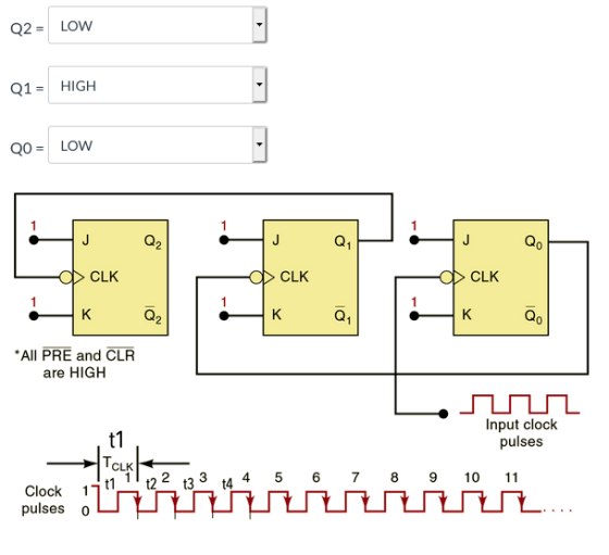
The following Flip Flops JK fix implements a binary counter; assuming that at time t1, all outputs Q are ZERO, it indicates the value of Q2, Q1 and Q0 at time t4.
Homework Answers
Here Q0 flip-flop is connected directly to clock. Also it's negative edge triggered flip-flop. Thus it will change on falling edge of clock.
Q1 changes when Q0 changes from 1 to 0 as it's clock is connected to Q0.
Q2 will change when Q1 changes from 1 to 0 as it's clock is connected to Q1.
Also all flip-flop will only toggle as it's input J=K=1.
Let's see with diagram

If you have any questions comment down and please? upvote thanks...
Add Answer to:
The following Flip Flops JK fix implements a binary counter;
assuming that at time t1, all...
Q D Clock Clk Q Clock Qb Q Qa Q Q Multiple type of flip-flops Circuit...
 Q D Clock Clk Q Clock Qb Q Qa Q Q Multiple type of flip-flops Circuit The figure above shows a circuit that use three different types of D flip-flops: a) D latch b) Rising-edge D flip-flop c) Falling-edge flip-flop For each one of the flip-flops enter their output for the times t1.t2.t3.t4 Assume that initially all outputs are '0' D
a. How many s are oquinst to build a binary counter that counts tihom 0 to 102" s Determine he fhroquensy at the outpst of the last FF of this counter for an input clock trequneney What is the...
 a. How many s are oquinst to build a binary counter that counts tihom 0 to 102" s Determine he fhroquensy at the outpst of the last FF of this counter for an input clock trequneney What is the counter's MOD number? d If the counter is initially at zero, what counter will it hold after 2060 pulses? 9 Cnsider the timing diagram shown below for JK Flip Flop (NOR), Complete the output waveform for Q clock IK Apply the...
please answer all thanks very much! Question 3 Shown below is a schematic diagram of a...
 please answer all thanks very much!
Question 3 Shown below is a schematic diagram of a counter made up of three JK flip-flops. (d) Shown below is a master-slave D flip-flop. This is made using two gated D latches. The truth table for a gated D latch is also shown below. HIGH J J CLK ас ас ac Truth table: gated D latch D EN D D, Q. D, 0. 0 0 go CLK ΕΝΟ ENO: 0 0 1 0...
please answer all thanks very much!
Question 3 Shown below is a schematic diagram of a counter made up of three JK flip-flops. (d) Shown below is a master-slave D flip-flop. This is made using two gated D latches. The truth table for a gated D latch is also shown below. HIGH J J CLK ас ас ac Truth table: gated D latch D EN D D, Q. D, 0. 0 0 go CLK ΕΝΟ ENO: 0 0 1 0...
23. A J-K flip-flop has a l on the J input and a 0 on the...
 23. A J-K flip-flop has a l on the J input and a 0 on the K input. What state is the flip-flop in? (a) Q=1,0-0 (b) Q-1, Q-1 (c) Q-0,Q 1 (d) Q-0,Q-0 -24. On a positive edge-triggered S-R flip-flop, the outputs reflect the input condition when (a) the clock pulse is LOW (b) the clock pulse is HIGH (c) the clock pulse transitions from LOW to HIGH (d) the clock pulse transitions from HIGH to LOW 25. The...
The initial state of Q.Q.Q2Q3 is 0000. As it has 4 flip flops, make a time...
 The initial state of Q.Q.Q2Q3 is 0000. As it has 4 flip flops, make a time diagram with the clock CK, CLR, Qo, Q1, Q2,Q3 for 16 cycles. Explain what the circuit does. Logic 1 c oa oºo- HH WE L.PRO EOCK LOCK TOCK ck Like 4k eta | 4
Design a 3- bit Multipurpose Register. The register utilizes 3 "D" type flip flops with outputs...
Design a 3- bit Multipurpose Register. The register utilizes 3 "D" type flip flops with outputs Q0, Q1, Q2. The Registers has a synchronous clock input(CLK) that clocks all 3 flip flops on its positive edge The Registers has an asynchronous clear input(CLR' ) that sets all flip flops to "0" when active low. The Register has 2 select inputs, S0 and S1 that selects the functions as folows: S1 = 0, 0, 1, 1 and S0 = 0,1,0,1 and...
Details,thanks! 12.(15 points) Design the sequence binary counter 0100: (11 10) using two D flip flops....
 Details,thanks!
12.(15 points) Design the sequence binary counter 0100: (11 10) using two D flip flops. Complete the State table (5 points) Implement the digital circuit (10 points) (It is not necessary to summarize the Boolean functions) a) b) Present state Next state 0 0 0 1. Q1 Clk Q Q0 Clock
Details,thanks!
12.(15 points) Design the sequence binary counter 0100: (11 10) using two D flip flops. Complete the State table (5 points) Implement the digital circuit (10 points) (It is not necessary to summarize the Boolean functions) a) b) Present state Next state 0 0 0 1. Q1 Clk Q Q0 Clock
Design a 4-bit binary up counter (like the following state diagram) using JK flip flops.
 Design a 4-bit binary up counter (like the following state diagram) using JK flip flops. State diagram. 0000 0001 11111 (a) Draw the state table with the input values for J K flip flops(b) Simplify the input equations by K map (c) Draw the logic diagram
*** please don't use handwriting 3. Determine the functional behavior of the circuit in the Figure....
 *** please don't use handwriting
3. Determine the functional behavior of the circuit in the Figure. Assume that input clk is driven by a square wave signal. [3 Marks] lo cot 11 011 clk Ko 01 Kq et Clear J. K JA K Q Q time clear T1 T2 T3 T4 4. Use T-Flip Flops and design counter that counts downward from 6+4+2and repeat again. Consider the next state for all states not in the counting sequence is 6. Fill...
*** please don't use handwriting
3. Determine the functional behavior of the circuit in the Figure. Assume that input clk is driven by a square wave signal. [3 Marks] lo cot 11 011 clk Ko 01 Kq et Clear J. K JA K Q Q time clear T1 T2 T3 T4 4. Use T-Flip Flops and design counter that counts downward from 6+4+2and repeat again. Consider the next state for all states not in the counting sequence is 6. Fill...
a) (5 marks) Explain the difference between a latch, a gated latch and a flip flop....
 a) (5 marks) Explain the difference between a latch, a gated latch and a flip flop. b) (5 marks) A gated SR latch has the following schematic diagram CLK a) Draw a timing diagram showing the Q and Q outputs for the following sequence of inputs: CLK R Assume that the initial state of the outputs is Q 0 and Q 1 c) (5 marks) Draw a schematic diagram for a rising edge-triggered master-slave D flip- flop built using two...
 Q D Clock Clk Q Clock Qb Q Qa Q Q Multiple type of flip-flops Circuit The figure above shows a circuit that use three different types of D flip-flops: a) D latch b) Rising-edge D flip-flop c) Falling-edge flip-flop For each one of the flip-flops enter their output for the times t1.t2.t3.t4 Assume that initially all outputs are '0' D
 a. How many s are oquinst to build a binary counter that counts tihom 0 to 102" s Determine he fhroquensy at the outpst of the last FF of this counter for an input clock trequneney What is the counter's MOD number? d If the counter is initially at zero, what counter will it hold after 2060 pulses? 9 Cnsider the timing diagram shown below for JK Flip Flop (NOR), Complete the output waveform for Q clock IK Apply the...
 please answer all thanks very much!
Question 3 Shown below is a schematic diagram of a counter made up of three JK flip-flops. (d) Shown below is a master-slave D flip-flop. This is made using two gated D latches. The truth table for a gated D latch is also shown below. HIGH J J CLK ас ас ac Truth table: gated D latch D EN D D, Q. D, 0. 0 0 go CLK ΕΝΟ ENO: 0 0 1 0...
please answer all thanks very much!
Question 3 Shown below is a schematic diagram of a counter made up of three JK flip-flops. (d) Shown below is a master-slave D flip-flop. This is made using two gated D latches. The truth table for a gated D latch is also shown below. HIGH J J CLK ас ас ac Truth table: gated D latch D EN D D, Q. D, 0. 0 0 go CLK ΕΝΟ ENO: 0 0 1 0...
 23. A J-K flip-flop has a l on the J input and a 0 on the K input. What state is the flip-flop in? (a) Q=1,0-0 (b) Q-1, Q-1 (c) Q-0,Q 1 (d) Q-0,Q-0 -24. On a positive edge-triggered S-R flip-flop, the outputs reflect the input condition when (a) the clock pulse is LOW (b) the clock pulse is HIGH (c) the clock pulse transitions from LOW to HIGH (d) the clock pulse transitions from HIGH to LOW 25. The...
 The initial state of Q.Q.Q2Q3 is 0000. As it has 4 flip flops, make a time diagram with the clock CK, CLR, Qo, Q1, Q2,Q3 for 16 cycles. Explain what the circuit does. Logic 1 c oa oºo- HH WE L.PRO EOCK LOCK TOCK ck Like 4k eta | 4
 Details,thanks!
12.(15 points) Design the sequence binary counter 0100: (11 10) using two D flip flops. Complete the State table (5 points) Implement the digital circuit (10 points) (It is not necessary to summarize the Boolean functions) a) b) Present state Next state 0 0 0 1. Q1 Clk Q Q0 Clock
Details,thanks!
12.(15 points) Design the sequence binary counter 0100: (11 10) using two D flip flops. Complete the State table (5 points) Implement the digital circuit (10 points) (It is not necessary to summarize the Boolean functions) a) b) Present state Next state 0 0 0 1. Q1 Clk Q Q0 Clock
 *** please don't use handwriting
3. Determine the functional behavior of the circuit in the Figure. Assume that input clk is driven by a square wave signal. [3 Marks] lo cot 11 011 clk Ko 01 Kq et Clear J. K JA K Q Q time clear T1 T2 T3 T4 4. Use T-Flip Flops and design counter that counts downward from 6+4+2and repeat again. Consider the next state for all states not in the counting sequence is 6. Fill...
*** please don't use handwriting
3. Determine the functional behavior of the circuit in the Figure. Assume that input clk is driven by a square wave signal. [3 Marks] lo cot 11 011 clk Ko 01 Kq et Clear J. K JA K Q Q time clear T1 T2 T3 T4 4. Use T-Flip Flops and design counter that counts downward from 6+4+2and repeat again. Consider the next state for all states not in the counting sequence is 6. Fill...
 a) (5 marks) Explain the difference between a latch, a gated latch and a flip flop. b) (5 marks) A gated SR latch has the following schematic diagram CLK a) Draw a timing diagram showing the Q and Q outputs for the following sequence of inputs: CLK R Assume that the initial state of the outputs is Q 0 and Q 1 c) (5 marks) Draw a schematic diagram for a rising edge-triggered master-slave D flip- flop built using two...
Most questions answered within 3 hours.
-
Coperto Insurers of Davenport, Iowa offers four different
insurance plans, all of which are equally popular...
asked 3 minutes ago -
In 2003, an organization surveyed 1 comma 510 adult Americans
and asked about a certain war,...
asked 1 minute ago -
A 50 mL graduated cylinder contains 25.0 mL of water. A 42.5040
g piece of gold...
asked 4 minutes ago -
Leo’s Lamp Store sells table and floor lamps. For a floor lamp,
the holding cost is...
asked 6 minutes ago -
Mark Gershon, owner of a musical instrument distributorship,
thinks that demand for guitars may be related...
asked 18 minutes ago -
Suppose that you were asked to construct a 95% confidence
interval based on the standard normal...
asked 26 minutes ago -
3 - What decimal number does the bit pattern 11001100 represent
if it is a:
•...
asked 28 minutes ago -
The copper(II) ion is acidic whereas the acetate ion is basic.
However, copper acetate is acidic....
asked 23 minutes ago -
A 48.53 mL volume of 1.00 M HCl was mixed with 47.70 mL of 2.00
M...
asked 45 minutes ago -
Neural cell types can be specified from ESCs with
retinoic acid, conditioned medium, co-cultures or by...
asked 50 minutes ago -
Can anyone solve: "Simulation with Arena 6th Edition - Chapter 8
- Question 3E"
8-3 Change...
asked 47 minutes ago -
What are some issues related to crimes, victims &
victimization that should be addressed?
asked 53 minutes ago