
Homework Answers


Add Answer to:
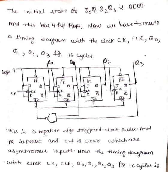
The initial state of Q.Q.Q2Q3 is 0000. As it has 4 flip flops, make a time...
The following Flip Flops JK fix implements a binary counter; assuming that at time t1, all...
 The following Flip Flops JK fix implements a binary counter;
assuming that at time t1, all outputs Q are ZERO, it indicates the
value of Q2, Q1 and Q0 at time t4.
Q2 = LOW . . Q1 = HIGH . QO = LOW 1 J Q2 J Q1 J QO CLK CLK CLK к Q2 K Q K Q. *All PRE and CLR are HIGH t1 Input clock pulses Talk t1 t2 2 +3 3 14 4 5 6...
The following Flip Flops JK fix implements a binary counter;
assuming that at time t1, all outputs Q are ZERO, it indicates the
value of Q2, Q1 and Q0 at time t4.
Q2 = LOW . . Q1 = HIGH . QO = LOW 1 J Q2 J Q1 J QO CLK CLK CLK к Q2 K Q K Q. *All PRE and CLR are HIGH t1 Input clock pulses Talk t1 t2 2 +3 3 14 4 5 6...
Design a 4-bit binary up counter (like the following state diagram) using JK flip flops.
 Design a 4-bit binary up counter (like the following state diagram) using JK flip flops. State diagram. 0000 0001 11111 (a) Draw the state table with the input values for J K flip flops(b) Simplify the input equations by K map (c) Draw the logic diagram
a) (5 marks) Explain the difference between a latch, a gated latch and a flip flop....
 a) (5 marks) Explain the difference between a latch, a gated latch and a flip flop. b) (5 marks) A gated SR latch has the following schematic diagram CLK a) Draw a timing diagram showing the Q and Q outputs for the following sequence of inputs: CLK R Assume that the initial state of the outputs is Q 0 and Q 1 c) (5 marks) Draw a schematic diagram for a rising edge-triggered master-slave D flip- flop built using two...
6. Design a 2-bit binary counter that counts, 0, 1, 2, 3, 0,. Use the 74LS374 IC, which has eight D flip-flops on it. They are positive-edge triggered, but it will not matter at all here You may draw...
 6. Design a 2-bit binary counter that counts, 0, 1, 2, 3, 0,. Use the 74LS374 IC, which has eight D flip-flops on it. They are positive-edge triggered, but it will not matter at all here You may draw a state diagram and then fill in the table Present State Q(t) Next State (D(t) - Q(t+1)) Q1(t) Qo(t) 7. Design a BCD binary counter that counts from 0 to 9 then back to 0 and repeat, displaying the count on...
Using Proteus, design Synchronous 4 bit Up binary counter using JK flip flops (Use 74HC76 JK flipflop). The circuit count from 0000 to 1111, etc.
 Q2) 4-bit Synchronous Counter Using Proteus, design Synchronous 4 bit Up binary counter using JK flip flops (Use 74HC76 JK flipflop). The circuit count from 0000 to 1111, etc. Experiment procedure: طريقة اجراء التجربة a) Complete the circuit. You can use external gates based on the following conditions: o Flipflop A switches every clock. o Flipflop B switches when the output of flipflop A=1 o Flipflop C switches when the outputs of A-B=1 o Flipflop D switches when the outputs of A=B=C=1 b) What is the typical feature of...
Design a BCD counter that uses four(4) T flip-flops using the given table format below. The...
 Design a BCD counter that uses four(4) T flip-flops using the given table format below. The output signal Y = 0 only during the counter transition from 1001 to 0000, otherwise, Y = 1 (for each valid input). Determine the following: (a) The circuit's state table Present State Next State Output Minterm Flip-Flop Inputs Q. Q4 Q1 Q: Q4 Q2 Q1 Y (m) T24 T02 TQ1 T08 Required format of the state table in Problem 2(a). Show table grid lines...
please show your work 4. Design a sequential circuit using D flip-flops that produces the following...
 please show your work
4. Design a sequential circuit using D flip-flops that produces the following state table: 1 Present Next QU Q.Qo Qu Q.Qo 0 00 XX 0 01 00 0 10 01 0 11 0 10 00 01 01 10 10 0 11 11 X XX 1 1 1 There are three bits of state split into a single bit Qu and an unsigned two-bit number Q1 Qo. You may assume that the counter does not start in...
please show your work
4. Design a sequential circuit using D flip-flops that produces the following state table: 1 Present Next QU Q.Qo Qu Q.Qo 0 00 XX 0 01 00 0 10 01 0 11 0 10 00 01 01 10 10 0 11 11 X XX 1 1 1 There are three bits of state split into a single bit Qu and an unsigned two-bit number Q1 Qo. You may assume that the counter does not start in...
Problem 2 Design a BCD counter that uses four(4) T flip-flops using the given table format...
 Problem 2 Design a BCD counter that uses four(4) T flip-flops using the given table format below. The output signal Y = 0 only during the counter transition from 1001 to 0000, otherwise, Y = 1 (for each valid input). Determine the following: (a) The circuit's state table 14 pts. Present State Next State Output Minterm Flip-Flop Inputs Q8 Q4 Q2 Q1 Q8Q4Q2 Y (m) TQ8 TQ4 TQ2 TQ1 Q1 Required format of the state table in Problem 2(a). Show...
Consider a 4-bit binary counter that increments on every clock pulse. (a) Construct the state diagram for a counter that has an state variable word A3A2A1A0. (b) Construct the state table by assuming...
Consider a 4-bit binary counter that increments on every clock pulse. (a) Construct the state diagram for a counter that has an state variable word A3A2A1A0. (b) Construct the state table by assuming that the circuit consists of four D-type flip-flops with the inputs D3, D2, D1, D0 corresponding to the outputs A3, A2, A1, A0, respectively. (c) Determine the Boolean equations for the flip-flop inputs as functions of the state variables A3, A2, A1, A0, respectively. (d) Design the...
Pre-Laboratorv Exercise: You are to design a state machine capable of controlling a 4-phase unipo...
 Pre-Laboratorv Exercise: You are to design a state machine capable of controlling a 4-phase unipolar stepper motor. This motor operates by energizing one (or more) of four coils of wire at a time to rotate a magnetized shaft to predetermined positions. Let us call the four coils A, B, C, and D. To make the motor rotate properly, the coils need to be turned on (driven at logic "1") and off (driven at logic "O") in the following sequence: ABCD-...
 The following Flip Flops JK fix implements a binary counter;
assuming that at time t1, all outputs Q are ZERO, it indicates the
value of Q2, Q1 and Q0 at time t4.
Q2 = LOW . . Q1 = HIGH . QO = LOW 1 J Q2 J Q1 J QO CLK CLK CLK к Q2 K Q K Q. *All PRE and CLR are HIGH t1 Input clock pulses Talk t1 t2 2 +3 3 14 4 5 6...
The following Flip Flops JK fix implements a binary counter;
assuming that at time t1, all outputs Q are ZERO, it indicates the
value of Q2, Q1 and Q0 at time t4.
Q2 = LOW . . Q1 = HIGH . QO = LOW 1 J Q2 J Q1 J QO CLK CLK CLK к Q2 K Q K Q. *All PRE and CLR are HIGH t1 Input clock pulses Talk t1 t2 2 +3 3 14 4 5 6...
 a) (5 marks) Explain the difference between a latch, a gated latch and a flip flop. b) (5 marks) A gated SR latch has the following schematic diagram CLK a) Draw a timing diagram showing the Q and Q outputs for the following sequence of inputs: CLK R Assume that the initial state of the outputs is Q 0 and Q 1 c) (5 marks) Draw a schematic diagram for a rising edge-triggered master-slave D flip- flop built using two...
 6. Design a 2-bit binary counter that counts, 0, 1, 2, 3, 0,. Use the 74LS374 IC, which has eight D flip-flops on it. They are positive-edge triggered, but it will not matter at all here You may draw a state diagram and then fill in the table Present State Q(t) Next State (D(t) - Q(t+1)) Q1(t) Qo(t) 7. Design a BCD binary counter that counts from 0 to 9 then back to 0 and repeat, displaying the count on...
 Design a BCD counter that uses four(4) T flip-flops using the given table format below. The output signal Y = 0 only during the counter transition from 1001 to 0000, otherwise, Y = 1 (for each valid input). Determine the following: (a) The circuit's state table Present State Next State Output Minterm Flip-Flop Inputs Q. Q4 Q1 Q: Q4 Q2 Q1 Y (m) T24 T02 TQ1 T08 Required format of the state table in Problem 2(a). Show table grid lines...
 please show your work
4. Design a sequential circuit using D flip-flops that produces the following state table: 1 Present Next QU Q.Qo Qu Q.Qo 0 00 XX 0 01 00 0 10 01 0 11 0 10 00 01 01 10 10 0 11 11 X XX 1 1 1 There are three bits of state split into a single bit Qu and an unsigned two-bit number Q1 Qo. You may assume that the counter does not start in...
please show your work
4. Design a sequential circuit using D flip-flops that produces the following state table: 1 Present Next QU Q.Qo Qu Q.Qo 0 00 XX 0 01 00 0 10 01 0 11 0 10 00 01 01 10 10 0 11 11 X XX 1 1 1 There are three bits of state split into a single bit Qu and an unsigned two-bit number Q1 Qo. You may assume that the counter does not start in...
 Problem 2 Design a BCD counter that uses four(4) T flip-flops using the given table format below. The output signal Y = 0 only during the counter transition from 1001 to 0000, otherwise, Y = 1 (for each valid input). Determine the following: (a) The circuit's state table 14 pts. Present State Next State Output Minterm Flip-Flop Inputs Q8 Q4 Q2 Q1 Q8Q4Q2 Y (m) TQ8 TQ4 TQ2 TQ1 Q1 Required format of the state table in Problem 2(a). Show...
 Pre-Laboratorv Exercise: You are to design a state machine capable of controlling a 4-phase unipolar stepper motor. This motor operates by energizing one (or more) of four coils of wire at a time to rotate a magnetized shaft to predetermined positions. Let us call the four coils A, B, C, and D. To make the motor rotate properly, the coils need to be turned on (driven at logic "1") and off (driven at logic "O") in the following sequence: ABCD-...
Most questions answered within 3 hours.
-
Question Three
Suppose you as project manager are using the Waterfall
development methodology on a large...
asked 22 minutes ago -
Which statement is not true about welfare in Canada?
A.Benefits typically vary based on one's ability...
asked 54 minutes ago -
Please help me with FLOWCHART and UML diagram for class,
thank you!
#include <iostream>
#include <fstream>...
asked 1 hour ago -
3. Describe the “logic circuit” of the Lac operon. Which
proteins are bound or not to...
asked 1 hour ago -
Ayesha’s adjusted gross income is $60,000 in 2019. She donated a
piece of artwork with a...
asked 1 hour ago -
For Dijkstra’s shortest path algorithm:
a. Give the Big-O time for Dijkstra’s shortest path algorithm
and...
asked 1 hour ago -
Phosphorus violates the 'octet rule' in biological molecules,
forming more covalent bonds than expected based on...
asked 2 hours ago -
A 1.3 eV electron has a 10-4 probability of tunneling
through a 2.4 eV potential barrier....
asked 2 hours ago -
What is the one ingredient that is common to being successful
with all stakeholders?
profit
trust...
asked 2 hours ago -
Write an assembly language 32 bit program that reads in lines of
text by a .txt...
asked 2 hours ago -
what is the density ( in g/L) of hydrogen gas at 29 degrees C and a...
asked 2 hours ago -
5-6. You are considering three investment alternatives for some
spare cash: Old Reliable Corporation stock (A1),...
asked 2 hours ago