
Homework Answers


Add Answer to:
6. Design a 2-bit binary counter that counts, 0, 1, 2, 3, 0,. Use the 74LS374 IC, which has eight D flip-flops on it. They are positive-edge triggered, but it will not matter at all here You may draw...
Design a three-bit counter using D flip-flops that has the following characteristics: When the value of...
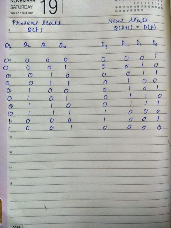
 Design a three-bit counter using D flip-flops that has the following characteristics: When the value of an input x is 0, the counter counts "down" in standard order. When the value of x is 1, the counter counts "up" in standard order a. First, complete the state table shown below Present State Next State Excitation 0 0 0 0 0 0 1 0 0 0 0 0 0 b. Next, derive the logic equations using the Karnaugh maps shown below...
(a) Design an asynchronous Binary Coded Decimal (BCD) count-up counter using JK flip-flops. Draw the counter circuit clearly showing the configuration of the JK flip-flops and the necessary logic gat...
 (a) Design an asynchronous Binary Coded Decimal (BCD) count-up counter using JK flip-flops. Draw the counter circuit clearly showing the configuration of the JK flip-flops and the necessary logic gate(s). Sketch the input and output waveforms of this counter (7 Marks) (b) The binary up/down counter for a cargo lift controller in a 7-storey building has an up-down (UID) control input and a buzzer output (B). The buzzer will sound B 1) when the lift is at level 1 or...
Design a two-bit up/down binary counter using D flip-flops that can count in binary from 0 to 7.
Design a two-bit up/down binary counter using D flip-flops that can count in binary from 0 to 7. When the control input x is 0, the circuit counts down, and when it is 1, the circuit counts up. (a) Obtain the state table of the two-bit counter. (b) Obtain the state diagram (c) Draw the logic diagram of the circuit.
Design a 5-bit binary counter using JK flip flops. Draw the flip-flop circuit diagram, the state...
Design a 5-bit binary counter using JK flip flops. Draw the flip-flop circuit diagram, the state graph, the timing diagram, the truth table (with clk pulse) and the state table (with present and next states).
Details,thanks! 12.(15 points) Design the sequence binary counter 0100: (11 10) using two D flip flops....
 Details,thanks!
12.(15 points) Design the sequence binary counter 0100: (11 10) using two D flip flops. Complete the State table (5 points) Implement the digital circuit (10 points) (It is not necessary to summarize the Boolean functions) a) b) Present state Next state 0 0 0 1. Q1 Clk Q Q0 Clock
Details,thanks!
12.(15 points) Design the sequence binary counter 0100: (11 10) using two D flip flops. Complete the State table (5 points) Implement the digital circuit (10 points) (It is not necessary to summarize the Boolean functions) a) b) Present state Next state 0 0 0 1. Q1 Clk Q Q0 Clock
Design a counter to count-up from 2 to 5 using 3 D Flip-Flops similar to the...
 Design a counter to count-up from 2 to 5 using 3 D Flip-Flops similar to the following sample: Important Steps: After you simplify D2, D1 and DO by kmap Have a piece of paper to draw it then open iCircuit to design it using BCD If it works well as a counter, copy the design from iCircuit and paste it here. 3-Bit Counter Using D Flip-Flop: The State Equation of D Flip-Flop: Q(t+1)=D(t) => Dn=An Count Up From 3 To...
1 Implement a bit 3 bit binary up counter using positive edge triggered D FF. 2...
1 Implement a bit 3 bit binary up counter using positive edge triggered D FF. 2 Design a 1001 sequence detector with D FF (Mealy model). 3 Design a 1001 sequence detector with D FF (Moore model). 4 Design a 4 bit universal shift register using D Flip Flops and MUX that implements the following functionality. S1 S0 Function 0 0 Shift Right 0 1 Hold 1 0 Load Value Parallelly 1 1 Shift Left
14. Design a cyclic counter that produces the binary sequence 0, 2, 3,1. o..if the control signal...
 14?
14. Design a cyclic counter that produces the binary sequence 0, 2, 3,1. o..if the control signal X is 0 but produces the binary sequence 0, 1,3,2.0, if the control signal X is1.Use D flip-flops. (a) Draw the state diagram; (6 points (b) Draw the input, present state-next state, excitation table: (6 points) (c) Derive the minimal SOP expressions for the D inputs of the flip-flops using K-maps. Draw the logic circuit realization of the counter, using only NAND...
14?
14. Design a cyclic counter that produces the binary sequence 0, 2, 3,1. o..if the control signal X is 0 but produces the binary sequence 0, 1,3,2.0, if the control signal X is1.Use D flip-flops. (a) Draw the state diagram; (6 points (b) Draw the input, present state-next state, excitation table: (6 points) (c) Derive the minimal SOP expressions for the D inputs of the flip-flops using K-maps. Draw the logic circuit realization of the counter, using only NAND...
Using S-R flip-flops, design a 3-bit counter (C,B,A) with the repeating binary counting sequence: 1, 3,...
Using S-R flip-flops, design a 3-bit counter (C,B,A) with the repeating binary counting sequence: 1, 3, 2, 6, 7, 5, 4. - Show the circuit's state table with the present-state entries in ascending order, which should have the present state (t), next state (t+1), and flip-flop inputs. - Find the flip-flop input equations for RC, RB, and RA in Product of Sums form.
Design a 2-bit counter using D Flip Flops that follows the sequence 0, 3, 2. Please...
Design a 2-bit counter using D Flip Flops that follows the sequence 0, 3, 2. Please provide explanation & Present/Future state table.
 Design a three-bit counter using D flip-flops that has the following characteristics: When the value of an input x is 0, the counter counts "down" in standard order. When the value of x is 1, the counter counts "up" in standard order a. First, complete the state table shown below Present State Next State Excitation 0 0 0 0 0 0 1 0 0 0 0 0 0 b. Next, derive the logic equations using the Karnaugh maps shown below...
 (a) Design an asynchronous Binary Coded Decimal (BCD) count-up counter using JK flip-flops. Draw the counter circuit clearly showing the configuration of the JK flip-flops and the necessary logic gate(s). Sketch the input and output waveforms of this counter (7 Marks) (b) The binary up/down counter for a cargo lift controller in a 7-storey building has an up-down (UID) control input and a buzzer output (B). The buzzer will sound B 1) when the lift is at level 1 or...
 Details,thanks!
12.(15 points) Design the sequence binary counter 0100: (11 10) using two D flip flops. Complete the State table (5 points) Implement the digital circuit (10 points) (It is not necessary to summarize the Boolean functions) a) b) Present state Next state 0 0 0 1. Q1 Clk Q Q0 Clock
Details,thanks!
12.(15 points) Design the sequence binary counter 0100: (11 10) using two D flip flops. Complete the State table (5 points) Implement the digital circuit (10 points) (It is not necessary to summarize the Boolean functions) a) b) Present state Next state 0 0 0 1. Q1 Clk Q Q0 Clock
 Design a counter to count-up from 2 to 5 using 3 D Flip-Flops similar to the following sample: Important Steps: After you simplify D2, D1 and DO by kmap Have a piece of paper to draw it then open iCircuit to design it using BCD If it works well as a counter, copy the design from iCircuit and paste it here. 3-Bit Counter Using D Flip-Flop: The State Equation of D Flip-Flop: Q(t+1)=D(t) => Dn=An Count Up From 3 To...
 14?
14. Design a cyclic counter that produces the binary sequence 0, 2, 3,1. o..if the control signal X is 0 but produces the binary sequence 0, 1,3,2.0, if the control signal X is1.Use D flip-flops. (a) Draw the state diagram; (6 points (b) Draw the input, present state-next state, excitation table: (6 points) (c) Derive the minimal SOP expressions for the D inputs of the flip-flops using K-maps. Draw the logic circuit realization of the counter, using only NAND...
14?
14. Design a cyclic counter that produces the binary sequence 0, 2, 3,1. o..if the control signal X is 0 but produces the binary sequence 0, 1,3,2.0, if the control signal X is1.Use D flip-flops. (a) Draw the state diagram; (6 points (b) Draw the input, present state-next state, excitation table: (6 points) (c) Derive the minimal SOP expressions for the D inputs of the flip-flops using K-maps. Draw the logic circuit realization of the counter, using only NAND...
Most questions answered within 3 hours.
-
Under the influence of its drive force, a snowmobile is moving
at a constant velocity along...
asked 25 seconds from now -
What mechanisms Drive speciation??
(I.e. what was Dawins theory on the orgin of species, and how...
asked 1 hour ago -
The manager at a car assembly plant believes that the mean
assembly time for a car...
asked 2 hours ago -
Which of the following is true of electron capture?
A) It decreases the nuclide's mass number...
asked 3 hours ago -
Assuming an efficiency of 43.10%, calculate the actual yield of
magnesium nitrate formed from 114.9 g...
asked 4 hours ago -
The highly pathogenic bacterium Clostridium
perfringens causes gangrene, a disease that results in the
destruction of...
asked 6 hours ago -
In the context of situation analysis, which of the following is
a category for analysis in...
asked 6 hours ago -
In a study of the gas phase decomposition of sulfuryl chloride
at 600 K SO2Cl2(g)SO2(g) +...
asked 6 hours ago -
75 g of 2-propanol (C3H8O) and 25 g of pentane are mixed in a
200 mL...
asked 6 hours ago -
The 2800-turn coil in a dc motor has an area per turn of 1.1 ×
10-2...
asked 6 hours ago -
Draw a combinational logic circuit diagram with a symbol inside
the box for two I/P of...
asked 6 hours ago -
The cliché we use quite a lot in finance is: there is a need to
maximize...
asked 6 hours ago