Design a two-bit up/down binary counter using D flip-flops that can count in binary from 0 to 7.
Design a two-bit up/down binary counter using D flip-flops that can count in binary from 0 to 7. When the control input x is 0, the circuit counts down, and when it is 1, the circuit counts up.
(a) Obtain the state table of the two-bit counter.
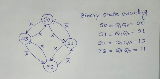
(b) Obtain the state diagram
(c) Draw the logic diagram of the circuit.
Homework Answers
(a) State Table
|
INPUT |
PRESENT STATE |
NEXT STATE |
||
|
X |
Q1 |
Q0 |
Q1+ |
Q0+ |
|
0 |
0 |
0 |
1 |
1 |
|
0 |
0 |
1 |
0 |
0 |
|
0 |
1 |
0 |
0 |
1 |
|
0 |
1 |
1 |
1 |
0 |
|
1 |
0 |
0 |
0 |
1 |
|
1 |
0 |
1 |
1 |
0 |
|
1 |
1 |
0 |
1 |
1 |
|
1 |
1 |
1 |
0 |
0 |
(b) State Diagram
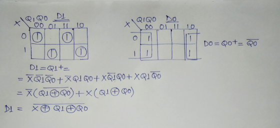
(c)

Add Answer to:
Design a two-bit up/down binary counter using D flip-flops that can count in binary from 0 to 7.
Please show process and I will rate faster!!! 2. Design a two-bit up/down binary counter using...
 Please show process and I will rate faster!!!
2. Design a two-bit up/down binary counter using T-fip-flops that can count in binary from 0 to 3. When the control input x is 0, the circuit counts up and when it is 1, the circuit counts down. (a) Obtain the state table of the two-bit counter (P. S., Input, N. S., Output). (b) Obtain the state diagram. (c) Draw the logic diagram of the circuit.
Please show process and I will rate faster!!!
2. Design a two-bit up/down binary counter using T-fip-flops that can count in binary from 0 to 3. When the control input x is 0, the circuit counts up and when it is 1, the circuit counts down. (a) Obtain the state table of the two-bit counter (P. S., Input, N. S., Output). (b) Obtain the state diagram. (c) Draw the logic diagram of the circuit.
(a) Design an asynchronous Binary Coded Decimal (BCD) count-up counter using JK flip-flops. Draw the counter circuit clearly showing the configuration of the JK flip-flops and the necessary logic gat...
 (a) Design an asynchronous Binary Coded Decimal (BCD) count-up counter using JK flip-flops. Draw the counter circuit clearly showing the configuration of the JK flip-flops and the necessary logic gate(s). Sketch the input and output waveforms of this counter (7 Marks) (b) The binary up/down counter for a cargo lift controller in a 7-storey building has an up-down (UID) control input and a buzzer output (B). The buzzer will sound B 1) when the lift is at level 1 or...
Design a 4-bit binary up counter (like the following state diagram) using JK flip flops.
 Design a 4-bit binary up counter (like the following state diagram) using JK flip flops. State diagram. 0000 0001 11111 (a) Draw the state table with the input values for J K flip flops(b) Simplify the input equations by K map (c) Draw the logic diagram
Up-Down counter with enable using JK flip-flops: Design, construct and test a 2-bit counter that counts up or down.
Up-Down counter with enable using JK flip-flops: Design, construct and test a 2-bit counter that counts up or down. An enable input E determines whether the counter is on or off. If E = 0, the counter is disabled and remains in the present count even though clock pulses are applied to the flip-flops. If E= 1, the counter in enabled and a second input, x, determines the count direction. If x= 1, the circuit counts up with the sequence...
Design an up/down counter with four states (0, 1, 2, 3) using clocked J-K flip-flops. A...
 Design an up/down counter with four states (0, 1, 2, 3) using clocked J-K flip-flops. A control signal x is used as follows: When x 0 the machine counts forward (up), when x , backward (down). Simulate using MultiSim and attach a simulation printout X Please address the following in your report 1. State Table 2. State Diagram 3. Flip-Flop Excitation Tables 4 K-Map Simplification and resulting diagram 5. Multisim Simulation 6. Conclusion/Discussion 7. References
Design an up/down counter with...
Design an up/down counter with four states (0, 1, 2, 3) using clocked J-K flip-flops. A control signal x is used as follows: When x 0 the machine counts forward (up), when x , backward (down). Simulate using MultiSim and attach a simulation printout X Please address the following in your report 1. State Table 2. State Diagram 3. Flip-Flop Excitation Tables 4 K-Map Simplification and resulting diagram 5. Multisim Simulation 6. Conclusion/Discussion 7. References
Design an up/down counter with...
Design a 5-bit binary counter using JK flip flops. Draw the flip-flop circuit diagram, the state...
Design a 5-bit binary counter using JK flip flops. Draw the flip-flop circuit diagram, the state graph, the timing diagram, the truth table (with clk pulse) and the state table (with present and next states).
a. Design a count up/count down counter that counts from 0 up to 4, then 4 down to 0 using D flip flop.
2. Synchronous Counters: a. Design a count up/count down counter that counts from 0 up to 4, then 4 down to 0 using D flip flop. b. Design a count up counter that counts from 0 up to 12 using JK flip flops.
Digital Logic Design Design a 0-9 counter using four D flip flops. The counter should run...
Digital Logic Design Design a 0-9 counter using four D flip flops. The counter should run on the SCLK output of the clock divider. It should have a four-bit binary output that increments from 0 to 9 one step on each clock cycle. When it reaches the value of 9, it should restart a 0 on the next clock cycle. Hint: consider using D flip flops with a reset input and using logic to reset the flip flops when the...
Design a three-bit counter using D flip-flops that has the following characteristics: When the value of...
 Design a three-bit counter using D flip-flops that has the following characteristics: When the value of an input x is 0, the counter counts "down" in standard order. When the value of x is 1, the counter counts "up" in standard order a. First, complete the state table shown below Present State Next State Excitation 0 0 0 0 0 0 1 0 0 0 0 0 0 b. Next, derive the logic equations using the Karnaugh maps shown below...
1) Design a synchronous 3-bit binary UP/DOWN counter uses the following counting pattern 10.2.3.7.6.40.1.3...) the counter...
 1) Design a synchronous 3-bit binary UP/DOWN counter uses the following counting pattern 10.2.3.7.6.40.1.3...) the counter will count in this pattern indefinitely when the input X is equal to 1. When the input the counter will reverse direction and count in the opposite pattern 0. 4 7310) Complete the state diagram, transition table, New state s and solve for the recitation equations for flipflops that will perform this function. (You do not need to draw the flip-flops Use the state...
 Please show process and I will rate faster!!!
2. Design a two-bit up/down binary counter using T-fip-flops that can count in binary from 0 to 3. When the control input x is 0, the circuit counts up and when it is 1, the circuit counts down. (a) Obtain the state table of the two-bit counter (P. S., Input, N. S., Output). (b) Obtain the state diagram. (c) Draw the logic diagram of the circuit.
Please show process and I will rate faster!!!
2. Design a two-bit up/down binary counter using T-fip-flops that can count in binary from 0 to 3. When the control input x is 0, the circuit counts up and when it is 1, the circuit counts down. (a) Obtain the state table of the two-bit counter (P. S., Input, N. S., Output). (b) Obtain the state diagram. (c) Draw the logic diagram of the circuit.
 (a) Design an asynchronous Binary Coded Decimal (BCD) count-up counter using JK flip-flops. Draw the counter circuit clearly showing the configuration of the JK flip-flops and the necessary logic gate(s). Sketch the input and output waveforms of this counter (7 Marks) (b) The binary up/down counter for a cargo lift controller in a 7-storey building has an up-down (UID) control input and a buzzer output (B). The buzzer will sound B 1) when the lift is at level 1 or...
 Design an up/down counter with four states (0, 1, 2, 3) using clocked J-K flip-flops. A control signal x is used as follows: When x 0 the machine counts forward (up), when x , backward (down). Simulate using MultiSim and attach a simulation printout X Please address the following in your report 1. State Table 2. State Diagram 3. Flip-Flop Excitation Tables 4 K-Map Simplification and resulting diagram 5. Multisim Simulation 6. Conclusion/Discussion 7. References
Design an up/down counter with...
Design an up/down counter with four states (0, 1, 2, 3) using clocked J-K flip-flops. A control signal x is used as follows: When x 0 the machine counts forward (up), when x , backward (down). Simulate using MultiSim and attach a simulation printout X Please address the following in your report 1. State Table 2. State Diagram 3. Flip-Flop Excitation Tables 4 K-Map Simplification and resulting diagram 5. Multisim Simulation 6. Conclusion/Discussion 7. References
Design an up/down counter with...
 Design a three-bit counter using D flip-flops that has the following characteristics: When the value of an input x is 0, the counter counts "down" in standard order. When the value of x is 1, the counter counts "up" in standard order a. First, complete the state table shown below Present State Next State Excitation 0 0 0 0 0 0 1 0 0 0 0 0 0 b. Next, derive the logic equations using the Karnaugh maps shown below...
 1) Design a synchronous 3-bit binary UP/DOWN counter uses the following counting pattern 10.2.3.7.6.40.1.3...) the counter will count in this pattern indefinitely when the input X is equal to 1. When the input the counter will reverse direction and count in the opposite pattern 0. 4 7310) Complete the state diagram, transition table, New state s and solve for the recitation equations for flipflops that will perform this function. (You do not need to draw the flip-flops Use the state...
Most questions answered within 3 hours.
-
Consider the following description:
"University consists of a number of schools. Each school offers
several distinct...
asked 1 minute from now -
Write a C++ program to manage a Point of Sale System for a
Supermarket. The main...
asked 7 minutes ago -
Lean was started as:
An offshoot of the quality movement after WWII
As Toyota wanted to...
asked 9 minutes ago -
5. Construct the full model with an LRAS, a SRAS, and an AD
curve. Discuss the...
asked 9 minutes ago -
Which of the following species can be regarded as electron
deficient? Justify your answer in terms...
asked 11 minutes ago -
At t=0 a grinding wheel has an angular velocity of 24.0 rad/s .
It has a...
asked 15 minutes ago -
Please explain the following problem. I've tried several
different approaches and nothing is working.
An electron...
asked 16 minutes ago -
A guitar string is 90 cm long and has a mass of 3.8 g . The...
asked 17 minutes ago -
Combustion of hydrocarbons such as ethane ( C 2 H 6 ) produces
carbon dioxide, a...
asked 43 minutes ago -
For the reaction: 2A + 3B ---> 3D, if the rate of formation
of D is...
asked 43 minutes ago -
At 25 °C, a solution has a hydronium ion concentration of
2.70×10⁻⁸ M.
What is the...
asked 59 minutes ago -
If gatsby wants to ensure that it can start each month with
sufficient denim on hand...
asked 56 minutes ago