
Homework Answers
1 & 3.
JK EXCITATION TABLE
|
PRESENT STATE |
NEXT STATE |
INPUT |
|
|
Q |
Q+ |
J |
K |
|
0 |
0 |
0 |
X |
|
0 |
1 |
1 |
X |
|
1 |
0 |
X |
1 |
|
1 |
1 |
X |
0 |
STATE TABLE
|
PRESENT STATE |
INPUT |
NEXT STATE |
JK FLIP FLOP EXCITATION INPUTs |
|||||
|
X |
Q1 |
Q0 |
Q1+ |
Q0+ |
J1 |
K1 |
J0 |
K0 |
|
0 |
0 |
0 |
0 |
1 |
0 |
X |
1 |
X |
|
0 |
0 |
1 |
1 |
0 |
1 |
X |
X |
1 |
|
0 |
1 |
0 |
1 |
1 |
X |
0 |
1 |
X |
|
0 |
1 |
1 |
0 |
0 |
X |
1 |
X |
1 |
|
1 |
0 |
0 |
1 |
1 |
1 |
X |
1 |
X |
|
1 |
0 |
1 |
0 |
0 |
0 |
X |
X |
1 |
|
1 |
1 |
0 |
0 |
1 |
X |
1 |
1 |
X |
|
1 |
1 |
1 |
1 |
0 |
X |
0 |
X |
1 |
2.
 5.
5.

Add Answer to:
Design an up/down counter with four states (0, 1, 2, 3) using clocked J-K flip-flops. A...
Design a two-bit up/down binary counter using D flip-flops that can count in binary from 0 to 7.
Design a two-bit up/down binary counter using D flip-flops that can count in binary from 0 to 7. When the control input x is 0, the circuit counts down, and when it is 1, the circuit counts up. (a) Obtain the state table of the two-bit counter. (b) Obtain the state diagram (c) Draw the logic diagram of the circuit.
UP/DOWN counter: Design a modulus-14 up/down counter using decade J-K flip-flops.
UP/DOWN counter: Design a modulus-14 up/down counter using decade J-K flip-flops.
a. Design a count up/count down counter that counts from 0 up to 4, then 4 down to 0 using D flip flop.
2. Synchronous Counters: a. Design a count up/count down counter that counts from 0 up to 4, then 4 down to 0 using D flip flop. b. Design a count up counter that counts from 0 up to 12 using JK flip flops.
(a) Design an asynchronous Binary Coded Decimal (BCD) count-up counter using JK flip-flops. Draw the counter circuit clearly showing the configuration of the JK flip-flops and the necessary logic gat...
 (a) Design an asynchronous Binary Coded Decimal (BCD) count-up counter using JK flip-flops. Draw the counter circuit clearly showing the configuration of the JK flip-flops and the necessary logic gate(s). Sketch the input and output waveforms of this counter (7 Marks) (b) The binary up/down counter for a cargo lift controller in a 7-storey building has an up-down (UID) control input and a buzzer output (B). The buzzer will sound B 1) when the lift is at level 1 or...
Up-Down counter with enable using JK flip-flops: Design, construct and test a 2-bit counter that counts up or down.
Up-Down counter with enable using JK flip-flops: Design, construct and test a 2-bit counter that counts up or down. An enable input E determines whether the counter is on or off. If E = 0, the counter is disabled and remains in the present count even though clock pulses are applied to the flip-flops. If E= 1, the counter in enabled and a second input, x, determines the count direction. If x= 1, the circuit counts up with the sequence...
Design a 4-bit binary up counter (like the following state diagram) using JK flip flops.
 Design a 4-bit binary up counter (like the following state diagram) using JK flip flops. State diagram. 0000 0001 11111 (a) Draw the state table with the input values for J K flip flops(b) Simplify the input equations by K map (c) Draw the logic diagram
Design a counter to count-up from 2 to 5 using 3 D Flip-Flops similar to the...
 Design a counter to count-up from 2 to 5 using 3 D Flip-Flops similar to the following sample: Important Steps: After you simplify D2, D1 and DO by kmap Have a piece of paper to draw it then open iCircuit to design it using BCD If it works well as a counter, copy the design from iCircuit and paste it here. 3-Bit Counter Using D Flip-Flop: The State Equation of D Flip-Flop: Q(t+1)=D(t) => Dn=An Count Up From 3 To...
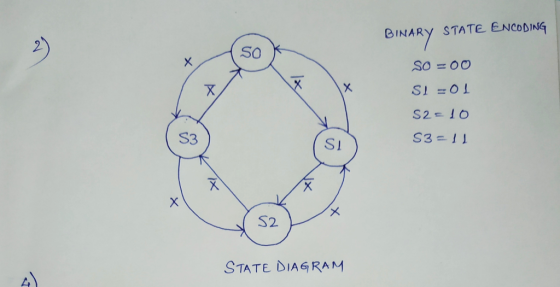
Design a synchronous counter that counts up 0, 1, 2, 3, 0, 1, 2, 3, ......
Design a synchronous counter that counts up 0, 1, 2, 3, 0, 1, 2, 3, ... when an input x = 1, and down when x = 0 using (a) D flip-flops. (b) J-K flip-flops. You need to show the state definition table, the state transition diagram, the state transition table, the K-maps for the respective logic functions and the schematic of the implementation using flipflops and logic gates in (a) as well as the K-maps for the logic functions...
Design a three-bit counter using D flip-flops that has the following characteristics: When the value of...
 Design a three-bit counter using D flip-flops that has the following characteristics: When the value of an input x is 0, the counter counts "down" in standard order. When the value of x is 1, the counter counts "up" in standard order a. First, complete the state table shown below Present State Next State Excitation 0 0 0 0 0 0 1 0 0 0 0 0 0 b. Next, derive the logic equations using the Karnaugh maps shown below...
assist please Design a 13-to-5 clocked synchronous counter using a Modulo-16 Up/Down Binary Counter. Show the...
 assist please
Design a 13-to-5 clocked synchronous counter using a Modulo-16 Up/Down Binary Counter. Show the state-transition table, excitation equations at the inputs of the counter, and logic diagram of the counter.
assist please
Design a 13-to-5 clocked synchronous counter using a Modulo-16 Up/Down Binary Counter. Show the state-transition table, excitation equations at the inputs of the counter, and logic diagram of the counter.
 (a) Design an asynchronous Binary Coded Decimal (BCD) count-up counter using JK flip-flops. Draw the counter circuit clearly showing the configuration of the JK flip-flops and the necessary logic gate(s). Sketch the input and output waveforms of this counter (7 Marks) (b) The binary up/down counter for a cargo lift controller in a 7-storey building has an up-down (UID) control input and a buzzer output (B). The buzzer will sound B 1) when the lift is at level 1 or...
 Design a counter to count-up from 2 to 5 using 3 D Flip-Flops similar to the following sample: Important Steps: After you simplify D2, D1 and DO by kmap Have a piece of paper to draw it then open iCircuit to design it using BCD If it works well as a counter, copy the design from iCircuit and paste it here. 3-Bit Counter Using D Flip-Flop: The State Equation of D Flip-Flop: Q(t+1)=D(t) => Dn=An Count Up From 3 To...
 Design a three-bit counter using D flip-flops that has the following characteristics: When the value of an input x is 0, the counter counts "down" in standard order. When the value of x is 1, the counter counts "up" in standard order a. First, complete the state table shown below Present State Next State Excitation 0 0 0 0 0 0 1 0 0 0 0 0 0 b. Next, derive the logic equations using the Karnaugh maps shown below...
 assist please
Design a 13-to-5 clocked synchronous counter using a Modulo-16 Up/Down Binary Counter. Show the state-transition table, excitation equations at the inputs of the counter, and logic diagram of the counter.
assist please
Design a 13-to-5 clocked synchronous counter using a Modulo-16 Up/Down Binary Counter. Show the state-transition table, excitation equations at the inputs of the counter, and logic diagram of the counter.
Most questions answered within 3 hours.
-
If the barometric pressure is 107.4 kPa, what is the pressure in
kPa of the gas...
asked 14 minutes ago -
A resonance tube can be used to measure the speed of sound in
air. A tuning...
asked 7 minutes ago -
Lourdes LLC. keeps a $100 change fund in its cash register. At
the end of the...
asked 12 minutes ago -
State the operation or control mechanism of TRIAC, DIAC, UJT, PUT,
GTO and IGBT.
asked 15 minutes ago -
Generator An AC generator supplies an rms voltage of 220 V at
50.0 Hz. It is...
asked 17 minutes ago -
Cars enter a car wash at a mean rate of 2 cars per half an hour....
asked 29 minutes ago -
Write SQL queries to answer the following question: A. Which
students are enrolled in Database and...
asked 42 minutes ago -
Required:
How was Dell computer working capital policy as a competitive
advantage? Write at least 200...
asked 25 minutes ago -
Your eye is 2.5 m away from a 60W light bulb that emits light in
all...
asked 32 minutes ago -
As a human and using your own human Intelligent Analysis (IA),
you would have noted that...
asked 34 minutes ago -
Transverse waves on a string have wave speed 8 m/s, amplitude
0.071 m, and wavelength 0.33...
asked 48 minutes ago -
At −11°C a sample of carbon monoxide gas exerts a pressure of
0.45 atm. What is...
asked 48 minutes ago