
Homework Answers


Add Answer to:
assist please
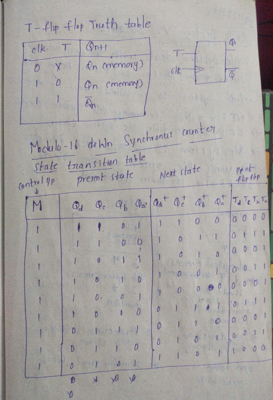
Design a 13-to-5 clocked synchronous counter using a Modulo-16 Up/Down Binary Counter. Show the...
[41 140 points En Reset Clock Analyze the clocked synchronous Modulo-8 Binary Counter [zyx] shown. The counter is initially reset at startup. Show the characteristic and excitation equations of t...
 [41 140 points En Reset Clock Analyze the clocked synchronous Modulo-8 Binary Counter [zyx] shown. The counter is initially reset at startup. Show the characteristic and excitation equations of the Enabled T Flip-Flops, as well the state-transition table. Draw the state diagram of the counter.
[41 140 points En Reset Clock Analyze the clocked synchronous Modulo-8 Binary Counter [zyx] shown. The counter is initially reset at startup. Show the characteristic and excitation equations of the Enabled T Flip-Flops, as well...
[41 140 points En Reset Clock Analyze the clocked synchronous Modulo-8 Binary Counter [zyx] shown. The counter is initially reset at startup. Show the characteristic and excitation equations of the Enabled T Flip-Flops, as well the state-transition table. Draw the state diagram of the counter.
[41 140 points En Reset Clock Analyze the clocked synchronous Modulo-8 Binary Counter [zyx] shown. The counter is initially reset at startup. Show the characteristic and excitation equations of the Enabled T Flip-Flops, as well...
Design a clocked synchronous counter with output sequence:
Design a clocked synchronous counter with output sequence: 1, 3, 5,7, 9,11, 13, 15, 14, 12, 10,8, 6,4, 2, 0, 1,.. using Enabled D Flip-Flops. Show the characteristic and excitation equations of the Flip-Flops, as well as the state-transition table and the logic diagram of the counter.
Design a modulo-11 up/down counter using a regular modulo-16 counter and any combinational logic. The modulo-11...
 Design a modulo-11 up/down counter using a regular modulo-16
counter and any combinational logic. The modulo-11 up/down counter
has four modes; count up by 1, count up by 2, count down by 1, and
no count. A formal description of the modulo-11 up/down counter is
shown below.
Inputs: ctrL0, ctrl-1 є {0, 1} State/Output:s (0,1, 10) The state transition function is defined as: s(t) if ctrl-0-0 and ctrl-1 = 0 (s(t)+ 1) mod 11 ifctl_0-0 and ctrl 1-1 s(t+1(s(t)+2) mod1...
Design a modulo-11 up/down counter using a regular modulo-16
counter and any combinational logic. The modulo-11 up/down counter
has four modes; count up by 1, count up by 2, count down by 1, and
no count. A formal description of the modulo-11 up/down counter is
shown below.
Inputs: ctrL0, ctrl-1 є {0, 1} State/Output:s (0,1, 10) The state transition function is defined as: s(t) if ctrl-0-0 and ctrl-1 = 0 (s(t)+ 1) mod 11 ifctl_0-0 and ctrl 1-1 s(t+1(s(t)+2) mod1...
Please show process and I will rate faster!!! 2. Design a two-bit up/down binary counter using...
 Please show process and I will rate faster!!!
2. Design a two-bit up/down binary counter using T-fip-flops that can count in binary from 0 to 3. When the control input x is 0, the circuit counts up and when it is 1, the circuit counts down. (a) Obtain the state table of the two-bit counter (P. S., Input, N. S., Output). (b) Obtain the state diagram. (c) Draw the logic diagram of the circuit.
Please show process and I will rate faster!!!
2. Design a two-bit up/down binary counter using T-fip-flops that can count in binary from 0 to 3. When the control input x is 0, the circuit counts up and when it is 1, the circuit counts down. (a) Obtain the state table of the two-bit counter (P. S., Input, N. S., Output). (b) Obtain the state diagram. (c) Draw the logic diagram of the circuit.
Design an up/down counter with four states (0, 1, 2, 3) using clocked J-K flip-flops. A...
 Design an up/down counter with four states (0, 1, 2, 3) using clocked J-K flip-flops. A control signal x is used as follows: When x 0 the machine counts forward (up), when x , backward (down). Simulate using MultiSim and attach a simulation printout X Please address the following in your report 1. State Table 2. State Diagram 3. Flip-Flop Excitation Tables 4 K-Map Simplification and resulting diagram 5. Multisim Simulation 6. Conclusion/Discussion 7. References
Design an up/down counter with...
Design an up/down counter with four states (0, 1, 2, 3) using clocked J-K flip-flops. A control signal x is used as follows: When x 0 the machine counts forward (up), when x , backward (down). Simulate using MultiSim and attach a simulation printout X Please address the following in your report 1. State Table 2. State Diagram 3. Flip-Flop Excitation Tables 4 K-Map Simplification and resulting diagram 5. Multisim Simulation 6. Conclusion/Discussion 7. References
Design an up/down counter with...
1) Design a synchronous 3-bit binary UP/DOWN counter uses the following counting pattern 10.2.3.7.6.40.1.3...) the counter...
 1) Design a synchronous 3-bit binary UP/DOWN counter uses the following counting pattern 10.2.3.7.6.40.1.3...) the counter will count in this pattern indefinitely when the input X is equal to 1. When the input the counter will reverse direction and count in the opposite pattern 0. 4 7310) Complete the state diagram, transition table, New state s and solve for the recitation equations for flipflops that will perform this function. (You do not need to draw the flip-flops Use the state...
ECEN3233 Digital Logic Design Name 3. Use a synchronous 4-bit binary up counter (with load and...
 ECEN3233 Digital Logic Design Name 3. Use a synchronous 4-bit binary up counter (with load and enable) to design a modulo-8 counter (also called offset counter) that begins with 0100, which means the counting sequence is: 0100-0101-0110->0111->1000->1001->1010->1011->0100-0101... Please complete your design using the figure on the next page. Use some logic gates if you need. (10 points) Enable Load Clock
Design a two-bit up/down binary counter using D flip-flops that can count in binary from 0 to 7.
Design a two-bit up/down binary counter using D flip-flops that can count in binary from 0 to 7. When the control input x is 0, the circuit counts down, and when it is 1, the circuit counts up. (a) Obtain the state table of the two-bit counter. (b) Obtain the state diagram (c) Draw the logic diagram of the circuit.
(a) Design an asynchronous Binary Coded Decimal (BCD) count-up counter using JK flip-flops. Draw the counter circuit clearly showing the configuration of the JK flip-flops and the necessary logic gat...
 (a) Design an asynchronous Binary Coded Decimal (BCD) count-up counter using JK flip-flops. Draw the counter circuit clearly showing the configuration of the JK flip-flops and the necessary logic gate(s). Sketch the input and output waveforms of this counter (7 Marks) (b) The binary up/down counter for a cargo lift controller in a 7-storey building has an up-down (UID) control input and a buzzer output (B). The buzzer will sound B 1) when the lift is at level 1 or...
It is a question about Computer organization Design a sequential up/down counter. The counter should count...
 It is a question about Computer organization
Design a sequential up/down counter. The counter should count as follows: When x -0, the counter will count 0, 1, 2, 3, 4, 5, 6, 7, 0,... When x 1, the counter will count 7, 6, 5, 4, 3, 2, 1, 0,7, .. 6.1. Draw the state diagram. 6.2. Draw the state table. 6. 6.3. Draw the excitation table using JK flip-flop. 6.4. Minimize. 6.5. Draw the logic diagram of your answer.
It is a question about Computer organization
Design a sequential up/down counter. The counter should count as follows: When x -0, the counter will count 0, 1, 2, 3, 4, 5, 6, 7, 0,... When x 1, the counter will count 7, 6, 5, 4, 3, 2, 1, 0,7, .. 6.1. Draw the state diagram. 6.2. Draw the state table. 6. 6.3. Draw the excitation table using JK flip-flop. 6.4. Minimize. 6.5. Draw the logic diagram of your answer.
 [41 140 points En Reset Clock Analyze the clocked synchronous Modulo-8 Binary Counter [zyx] shown. The counter is initially reset at startup. Show the characteristic and excitation equations of the Enabled T Flip-Flops, as well the state-transition table. Draw the state diagram of the counter.
[41 140 points En Reset Clock Analyze the clocked synchronous Modulo-8 Binary Counter [zyx] shown. The counter is initially reset at startup. Show the characteristic and excitation equations of the Enabled T Flip-Flops, as well...
[41 140 points En Reset Clock Analyze the clocked synchronous Modulo-8 Binary Counter [zyx] shown. The counter is initially reset at startup. Show the characteristic and excitation equations of the Enabled T Flip-Flops, as well the state-transition table. Draw the state diagram of the counter.
[41 140 points En Reset Clock Analyze the clocked synchronous Modulo-8 Binary Counter [zyx] shown. The counter is initially reset at startup. Show the characteristic and excitation equations of the Enabled T Flip-Flops, as well...
 Design a modulo-11 up/down counter using a regular modulo-16
counter and any combinational logic. The modulo-11 up/down counter
has four modes; count up by 1, count up by 2, count down by 1, and
no count. A formal description of the modulo-11 up/down counter is
shown below.
Inputs: ctrL0, ctrl-1 є {0, 1} State/Output:s (0,1, 10) The state transition function is defined as: s(t) if ctrl-0-0 and ctrl-1 = 0 (s(t)+ 1) mod 11 ifctl_0-0 and ctrl 1-1 s(t+1(s(t)+2) mod1...
Design a modulo-11 up/down counter using a regular modulo-16
counter and any combinational logic. The modulo-11 up/down counter
has four modes; count up by 1, count up by 2, count down by 1, and
no count. A formal description of the modulo-11 up/down counter is
shown below.
Inputs: ctrL0, ctrl-1 є {0, 1} State/Output:s (0,1, 10) The state transition function is defined as: s(t) if ctrl-0-0 and ctrl-1 = 0 (s(t)+ 1) mod 11 ifctl_0-0 and ctrl 1-1 s(t+1(s(t)+2) mod1...
 Please show process and I will rate faster!!!
2. Design a two-bit up/down binary counter using T-fip-flops that can count in binary from 0 to 3. When the control input x is 0, the circuit counts up and when it is 1, the circuit counts down. (a) Obtain the state table of the two-bit counter (P. S., Input, N. S., Output). (b) Obtain the state diagram. (c) Draw the logic diagram of the circuit.
Please show process and I will rate faster!!!
2. Design a two-bit up/down binary counter using T-fip-flops that can count in binary from 0 to 3. When the control input x is 0, the circuit counts up and when it is 1, the circuit counts down. (a) Obtain the state table of the two-bit counter (P. S., Input, N. S., Output). (b) Obtain the state diagram. (c) Draw the logic diagram of the circuit.
 Design an up/down counter with four states (0, 1, 2, 3) using clocked J-K flip-flops. A control signal x is used as follows: When x 0 the machine counts forward (up), when x , backward (down). Simulate using MultiSim and attach a simulation printout X Please address the following in your report 1. State Table 2. State Diagram 3. Flip-Flop Excitation Tables 4 K-Map Simplification and resulting diagram 5. Multisim Simulation 6. Conclusion/Discussion 7. References
Design an up/down counter with...
Design an up/down counter with four states (0, 1, 2, 3) using clocked J-K flip-flops. A control signal x is used as follows: When x 0 the machine counts forward (up), when x , backward (down). Simulate using MultiSim and attach a simulation printout X Please address the following in your report 1. State Table 2. State Diagram 3. Flip-Flop Excitation Tables 4 K-Map Simplification and resulting diagram 5. Multisim Simulation 6. Conclusion/Discussion 7. References
Design an up/down counter with...
 1) Design a synchronous 3-bit binary UP/DOWN counter uses the following counting pattern 10.2.3.7.6.40.1.3...) the counter will count in this pattern indefinitely when the input X is equal to 1. When the input the counter will reverse direction and count in the opposite pattern 0. 4 7310) Complete the state diagram, transition table, New state s and solve for the recitation equations for flipflops that will perform this function. (You do not need to draw the flip-flops Use the state...
 ECEN3233 Digital Logic Design Name 3. Use a synchronous 4-bit binary up counter (with load and enable) to design a modulo-8 counter (also called offset counter) that begins with 0100, which means the counting sequence is: 0100-0101-0110->0111->1000->1001->1010->1011->0100-0101... Please complete your design using the figure on the next page. Use some logic gates if you need. (10 points) Enable Load Clock
 (a) Design an asynchronous Binary Coded Decimal (BCD) count-up counter using JK flip-flops. Draw the counter circuit clearly showing the configuration of the JK flip-flops and the necessary logic gate(s). Sketch the input and output waveforms of this counter (7 Marks) (b) The binary up/down counter for a cargo lift controller in a 7-storey building has an up-down (UID) control input and a buzzer output (B). The buzzer will sound B 1) when the lift is at level 1 or...
 It is a question about Computer organization
Design a sequential up/down counter. The counter should count as follows: When x -0, the counter will count 0, 1, 2, 3, 4, 5, 6, 7, 0,... When x 1, the counter will count 7, 6, 5, 4, 3, 2, 1, 0,7, .. 6.1. Draw the state diagram. 6.2. Draw the state table. 6. 6.3. Draw the excitation table using JK flip-flop. 6.4. Minimize. 6.5. Draw the logic diagram of your answer.
It is a question about Computer organization
Design a sequential up/down counter. The counter should count as follows: When x -0, the counter will count 0, 1, 2, 3, 4, 5, 6, 7, 0,... When x 1, the counter will count 7, 6, 5, 4, 3, 2, 1, 0,7, .. 6.1. Draw the state diagram. 6.2. Draw the state table. 6. 6.3. Draw the excitation table using JK flip-flop. 6.4. Minimize. 6.5. Draw the logic diagram of your answer.
Most questions answered within 3 hours.
-
The stockholders’ equity section of Concord Corporation’s
balance sheet at December 31 is presented here.
CONCORD...
asked 13 seconds ago -
many biochemical dissolve in the aqueous media of the cell. What
does this imply about the...
asked 8 minutes ago -
In hypothesis testing, it is easier to reject H0 with
a ______________
directional test (one tail)...
asked 6 minutes ago -
Explain how to uphold conditions relating to the work environment,
equipment, materials, procedures and special requirements
asked 6 minutes ago -
The probability of a manufacturing defect in an aluminum
beverage can is .00008 if 100,600 cans...
asked 10 minutes ago -
Which aqueous solution below is most acidic?
a. pH= 3.00
c. [-OH]= 2 x 10^-3
b....
asked 32 minutes ago -
There are four (4) major financial statements: Income Statement,
Retained Earning (Owner's Equity) Statement, Balance Sheet,...
asked 38 minutes ago -
A) Banana, Inc. has a book value per share of $8.70, earnings
per share of $1.68,...
asked 38 minutes ago -
a.)Suppose you were
preparing 1.0 L of a bleaching solution in a volumetric flask, and
it...
asked 48 minutes ago -
write a personal statement of 500 words on the impact you strive
to make using a...
asked 40 minutes ago -
At 25.0 mL sample of 0.100 M HClO (aq) is titrated with NaOH
(aq). What is...
asked 55 minutes ago -
Mark launders his white clothes using the production
function
q=2B +G,
where B is the number...
asked 1 hour ago