Consider a 4-bit binary counter that increments on every clock pulse. (a) Construct the state diagram for a counter that has an state variable word A3A2A1A0. (b) Construct the state table by assuming...
Consider a 4-bit binary counter that increments on every clock pulse.
(a) Construct the state diagram for a counter that has an state variable word A3A2A1A0.
(b) Construct the state table by assuming that the circuit consists of four D-type flip-flops with the inputs D3, D2, D1, D0 corresponding to the outputs A3, A2, A1, A0, respectively.
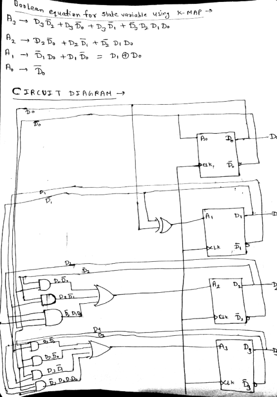
(c) Determine the Boolean equations for the flip-flop inputs as functions of the state variables A3, A2, A1, A0, respectively.
(d) Design the PLA-based circuit diagram for this counter.
Homework Answers

Add Answer to:
Consider a 4-bit binary counter that increments on every clock pulse. (a) Construct the state diagram for a counter that has an state variable word A3A2A1A0. (b) Construct the state table by assuming...
5. Consider a 4-bit binary counter that increments on every clock pulse. (20pts) (a) Construct the...
 5. Consider a 4-bit binary counter that increments on every clock pulse. (20pts) (a) Construct the state diagram for a counter that has an state variable word A3A2AiAo (b) Construct the state table by assuming that the circuit consists of four D-type flip-flops with the inputs D3, D2, Di, Do corresponding to the outputs A3, A2, Ai, Ao, respectively. (c) Determine the Boolean equations for the flip-flop inputs as functions of the state variables A3, A2, A, Ao, respectively. (d)...
Design a 5-bit binary counter using JK flip flops. Draw the flip-flop circuit diagram, the state...
Design a 5-bit binary counter using JK flip flops. Draw the flip-flop circuit diagram, the state graph, the timing diagram, the truth table (with clk pulse) and the state table (with present and next states).
Design a counter to count-up from 2 to 5 using 3 D Flip-Flops similar to the...
 Design a counter to count-up from 2 to 5 using 3 D Flip-Flops similar to the following sample: Important Steps: After you simplify D2, D1 and DO by kmap Have a piece of paper to draw it then open iCircuit to design it using BCD If it works well as a counter, copy the design from iCircuit and paste it here. 3-Bit Counter Using D Flip-Flop: The State Equation of D Flip-Flop: Q(t+1)=D(t) => Dn=An Count Up From 3 To...
Design a data processor, which keeps counting under given conditions. You will use an Algorithmic State...
Design a data processor, which keeps counting under given conditions. You will use an Algorithmic State Machine (ASM) chart, which will define its digital hardware algorithm. Design a digital system with two flip-flops, E and F, and one 4-bit binary counter, A. The individual flip-flops in A are denoted by A4, A3, A2, and A1, with A4 holding the MSB of the count. A start signal S initiates the system operation by clearing the counter A and flip-flop F. The...
The following is an equivalent way of creating the circuit above. Below is the truth table...
 The following is an equivalent way of creating the circuit
above.
Below is the truth table
Q2, Q1, and Q0 are LED outputs from left to right respectively
and D2, D1, and D0 are switches from left to right respectively
Answer the following questions:
1. What signal(s) represent the present state and next state of
the circuit?
2. Sketch a Finite State Machine diagram of the circuit (Be sure
to show inputs and outputs).
3. Describe the high-level behavior of...
The following is an equivalent way of creating the circuit
above.
Below is the truth table
Q2, Q1, and Q0 are LED outputs from left to right respectively
and D2, D1, and D0 are switches from left to right respectively
Answer the following questions:
1. What signal(s) represent the present state and next state of
the circuit?
2. Sketch a Finite State Machine diagram of the circuit (Be sure
to show inputs and outputs).
3. Describe the high-level behavior of...
Design a 4-bit binary up counter (like the following state diagram) using JK flip flops.
 Design a 4-bit binary up counter (like the following state diagram) using JK flip flops. State diagram. 0000 0001 11111 (a) Draw the state table with the input values for J K flip flops(b) Simplify the input equations by K map (c) Draw the logic diagram
The task is to design a two-bit controlled counter which has two counting bits (Q2, Q1), has one control input C1, and a...
 The task is to design a two-bit controlled counter which has two
counting bits (Q2, Q1), has one control input C1, and also two
extra outputs, one indicating overflow, the other underflow.
When C1=0 the counter counts up by 2s; i.e. 0 becomes 2, 1
becomes 3. In this mode the values 2 and 3 go to the overflow
state. When the control input C1=1, the counter counts down by 2s,
i.e. 3 becomes 1, and 2 becomes 0, and...
The task is to design a two-bit controlled counter which has two
counting bits (Q2, Q1), has one control input C1, and also two
extra outputs, one indicating overflow, the other underflow.
When C1=0 the counter counts up by 2s; i.e. 0 becomes 2, 1
becomes 3. In this mode the values 2 and 3 go to the overflow
state. When the control input C1=1, the counter counts down by 2s,
i.e. 3 becomes 1, and 2 becomes 0, and...
1. Suppose you want to design a 2-bit binary up-counter. Construct the state table using A1...
 1. Suppose you want to design a 2-bit binary up-counter. Construct the state table using A1 and AO as the previous state of bits and A1+, A0+ as the next bit states, ie, to count from 00 to 01, A1 stays at 0, but AO changes from 0 to 1. Let the counter wrap-around, such that 11 -> 00. Draw the state diagram. 2. Next, add in a third input, En, for enable. The counter can only count up when...
WRITE THE CODE IN VERILOG: Instead of using Registers, USE D FLIP FLOPS and a clock....
 WRITE THE CODE IN VERILOG: Instead of using Registers, USE D
FLIP FLOPS and a clock. Include the logic for a reset
A sequential circuit with three D flip-flops A, B, and C, a trigger x, and an output z1, and zo. On this state machine diagram, the label of the states are in the order of (ABC), the transition is the one bit x, and the output is under the forward slash. x/z1zo. The start state is 001 0/01...
WRITE THE CODE IN VERILOG: Instead of using Registers, USE D
FLIP FLOPS and a clock. Include the logic for a reset
A sequential circuit with three D flip-flops A, B, and C, a trigger x, and an output z1, and zo. On this state machine diagram, the label of the states are in the order of (ABC), the transition is the one bit x, and the output is under the forward slash. x/z1zo. The start state is 001 0/01...
Using Proteus, design Synchronous 4 bit Up binary counter using JK flip flops (Use 74HC76 JK flipflop). The circuit count from 0000 to 1111, etc.
 Q2) 4-bit Synchronous Counter Using Proteus, design Synchronous 4 bit Up binary counter using JK flip flops (Use 74HC76 JK flipflop). The circuit count from 0000 to 1111, etc. Experiment procedure: طريقة اجراء التجربة a) Complete the circuit. You can use external gates based on the following conditions: o Flipflop A switches every clock. o Flipflop B switches when the output of flipflop A=1 o Flipflop C switches when the outputs of A-B=1 o Flipflop D switches when the outputs of A=B=C=1 b) What is the typical feature of...
 5. Consider a 4-bit binary counter that increments on every clock pulse. (20pts) (a) Construct the state diagram for a counter that has an state variable word A3A2AiAo (b) Construct the state table by assuming that the circuit consists of four D-type flip-flops with the inputs D3, D2, Di, Do corresponding to the outputs A3, A2, Ai, Ao, respectively. (c) Determine the Boolean equations for the flip-flop inputs as functions of the state variables A3, A2, A, Ao, respectively. (d)...
 Design a counter to count-up from 2 to 5 using 3 D Flip-Flops similar to the following sample: Important Steps: After you simplify D2, D1 and DO by kmap Have a piece of paper to draw it then open iCircuit to design it using BCD If it works well as a counter, copy the design from iCircuit and paste it here. 3-Bit Counter Using D Flip-Flop: The State Equation of D Flip-Flop: Q(t+1)=D(t) => Dn=An Count Up From 3 To...
 The following is an equivalent way of creating the circuit
above.
Below is the truth table
Q2, Q1, and Q0 are LED outputs from left to right respectively
and D2, D1, and D0 are switches from left to right respectively
Answer the following questions:
1. What signal(s) represent the present state and next state of
the circuit?
2. Sketch a Finite State Machine diagram of the circuit (Be sure
to show inputs and outputs).
3. Describe the high-level behavior of...
The following is an equivalent way of creating the circuit
above.
Below is the truth table
Q2, Q1, and Q0 are LED outputs from left to right respectively
and D2, D1, and D0 are switches from left to right respectively
Answer the following questions:
1. What signal(s) represent the present state and next state of
the circuit?
2. Sketch a Finite State Machine diagram of the circuit (Be sure
to show inputs and outputs).
3. Describe the high-level behavior of...
 The task is to design a two-bit controlled counter which has two
counting bits (Q2, Q1), has one control input C1, and also two
extra outputs, one indicating overflow, the other underflow.
When C1=0 the counter counts up by 2s; i.e. 0 becomes 2, 1
becomes 3. In this mode the values 2 and 3 go to the overflow
state. When the control input C1=1, the counter counts down by 2s,
i.e. 3 becomes 1, and 2 becomes 0, and...
The task is to design a two-bit controlled counter which has two
counting bits (Q2, Q1), has one control input C1, and also two
extra outputs, one indicating overflow, the other underflow.
When C1=0 the counter counts up by 2s; i.e. 0 becomes 2, 1
becomes 3. In this mode the values 2 and 3 go to the overflow
state. When the control input C1=1, the counter counts down by 2s,
i.e. 3 becomes 1, and 2 becomes 0, and...
 1. Suppose you want to design a 2-bit binary up-counter. Construct the state table using A1 and AO as the previous state of bits and A1+, A0+ as the next bit states, ie, to count from 00 to 01, A1 stays at 0, but AO changes from 0 to 1. Let the counter wrap-around, such that 11 -> 00. Draw the state diagram. 2. Next, add in a third input, En, for enable. The counter can only count up when...
 WRITE THE CODE IN VERILOG: Instead of using Registers, USE D
FLIP FLOPS and a clock. Include the logic for a reset
A sequential circuit with three D flip-flops A, B, and C, a trigger x, and an output z1, and zo. On this state machine diagram, the label of the states are in the order of (ABC), the transition is the one bit x, and the output is under the forward slash. x/z1zo. The start state is 001 0/01...
WRITE THE CODE IN VERILOG: Instead of using Registers, USE D
FLIP FLOPS and a clock. Include the logic for a reset
A sequential circuit with three D flip-flops A, B, and C, a trigger x, and an output z1, and zo. On this state machine diagram, the label of the states are in the order of (ABC), the transition is the one bit x, and the output is under the forward slash. x/z1zo. The start state is 001 0/01...
Most questions answered within 3 hours.
-
A bicyclist starting at rest produces a constant angular
acceleration of 1.10 rad/s2 for wheels that...
asked 3 minutes ago -
The
half-life of a radioactive source is 14.0 minutes. How much time
must elapse before the...
asked 1 minute ago -
Given P(Ec ) = 0.43, P(F) = 0.52, and P(EF) = 0.18.
Find P( E |...
asked 48 minutes ago -
Consider two empty containers A and B whose volumes are
10mL and 20mL respectively. 1mL of...
asked 51 minutes ago -
QUESTION 6
Determine the linear momentum of a 2,800 kg houseboat going 3
m/s.
9,100 kg.m/s...
asked 1 hour ago -
Jor-el throws a ball upward from the top of a 728 foot building
on the planet...
asked 1 hour ago -
Which of the following will most likely to happen if Federal
Reserve Bank decreases the money...
asked 52 minutes ago -
You’ve just joined the investment banking firm of Dewey,
Cheatum, and Howe. They’ve offered you two...
asked 46 minutes ago -
An air conditioner cools 226 m^3/min of humid air at 36 oC and
98% relative humidity...
asked 45 minutes ago -
Vaughn Manufacturing acquires a coal mine at a cost of $1870000.
Intangible development costs total $354000....
asked 55 minutes ago -
Question 5
What effect would a decrease in
temperature have on pressure, assuming that volume
(T)...
asked 1 hour ago -
Draw the Lewis dot structures for the following molecules. None
of the atoms have a formal...
asked 1 hour ago