Please do not answer if you are going to copy the answers of others. Only do it if you know how. The others are wrong.

Homework Answers


Add Answer to:
Please do not answer if you are going to copy the answers of
others. Only do...
8. Consider the circuit shown in Figure 7. A Q-point value for Ic between a minimum of 4 mA and a maximum of 5 mA is required. Assume that resistor values are constant and that B ranges from 100 to...
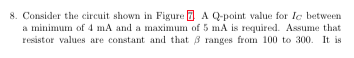
 8. Consider the circuit shown in Figure 7. A Q-point value for Ic between a minimum of 4 mA and a maximum of 5 mA is required. Assume that resistor values are constant and that B ranges from 100 to 300. It is desired for RB to have the largest possible value while meeting the other constraints. (a) Determine the values of RB and RE. +15 V Figure 7
8. Consider the circuit shown in Figure 7. A Q-point value...
8. Consider the circuit shown in Figure 7. A Q-point value for Ic between a minimum of 4 mA and a maximum of 5 mA is required. Assume that resistor values are constant and that B ranges from 100 to 300. It is desired for RB to have the largest possible value while meeting the other constraints. (a) Determine the values of RB and RE. +15 V Figure 7
8. Consider the circuit shown in Figure 7. A Q-point value...
can anyone help with c? 8. Consider the circuit shown in Figure 7. A Q-point value for Ic between a minimum of 4 mA and a maximum of 5 mA is required. Assume that resistor values are constant and tha...
 can anyone help with c?
8. Consider the circuit shown in Figure 7. A Q-point value for Ic between a minimum of 4 mA and a maximum of 5 mA is required. Assume that resistor values are constant and that B ranges from 100 to 300. It is desired for RB to have the largest possible value while meeting the othei constraints. (a) Determine the values of RB and RE. (b) Explain the contribution of resistor Re for thermal stabilisation...
can anyone help with c?
8. Consider the circuit shown in Figure 7. A Q-point value for Ic between a minimum of 4 mA and a maximum of 5 mA is required. Assume that resistor values are constant and that B ranges from 100 to 300. It is desired for RB to have the largest possible value while meeting the othei constraints. (a) Determine the values of RB and RE. (b) Explain the contribution of resistor Re for thermal stabilisation...
Consider the circuit shown in Figure 1. A Q-point value for IC between a minimum of 4 mA and a maximum of 5 mA is required. Assume that resistor values are constant and that β ranges from 100 to 300....
 Consider the circuit shown in Figure 1. A Q-point value for IC
between a minimum of 4 mA and a maximum of 5 mA is required. Assume
that resistor values are constant and that β ranges from 100 to
300. It is desired for RB to have the largest possible value while
meeting the other constraints.
(a) Determine the values of RB and RE.
(b) Explain the contribution of resistor RE for thermal
stabilisation of this circuit (Thermal stabilisation -...
Consider the circuit shown in Figure 1. A Q-point value for IC
between a minimum of 4 mA and a maximum of 5 mA is required. Assume
that resistor values are constant and that β ranges from 100 to
300. It is desired for RB to have the largest possible value while
meeting the other constraints.
(a) Determine the values of RB and RE.
(b) Explain the contribution of resistor RE for thermal
stabilisation of this circuit (Thermal stabilisation -...
Download the datasheet for 2N3904 and find the value of Bp. (Hint: Use average value) Be=...
 Download the datasheet for 2N3904 and find the value of Bp. (Hint: Use average value) Be= Voc +10 V RB We are going to consider the common emitter configuration circuit shown in the figure to test a 2N3904 npn Bipolar Junction Transistor (BJT) under DC bias conditions. Your circuit should place a fixed collector resistor, Rc, in the circuit to prevent the collector current, Ic, from exceeding 40 mA (for this, you know that the minimum value of is zero)....
Help please? Q-21.5 Unanswered An inductor (L = 400 mH), a capacitor (C = 4.43 uF),...
 Help please?
Q-21.5 Unanswered An inductor (L = 400 mH), a capacitor (C = 4.43 uF), and a resistor (R = 500 ) are connected in series. A 58.0 Hz AC generator connected in series to these elements produces a maximum current of 200 mA in the circuit. Calculate the required maximum voltage AVmax. 138 A 144 v 138 V 144 mv Q-21.6 Unanswered An inductor (L = 400 mH), a capacitor (C = 4.43 uF), and a resistor (R...
Help please?
Q-21.5 Unanswered An inductor (L = 400 mH), a capacitor (C = 4.43 uF), and a resistor (R = 500 ) are connected in series. A 58.0 Hz AC generator connected in series to these elements produces a maximum current of 200 mA in the circuit. Calculate the required maximum voltage AVmax. 138 A 144 v 138 V 144 mv Q-21.6 Unanswered An inductor (L = 400 mH), a capacitor (C = 4.43 uF), and a resistor (R...
Consider the circuit shown in the figure, where 1 = 21.7 V, 2 = 14.3 V,...
 Consider the circuit shown in
the figure, where 1 = 21.7 V,
2 = 14.3 V,
and R = 12.0 Ω.
I'm not sure I understand Kirchhoff's Law and how to apply it to
a problem like this.
Consider the circuit shown in the figure, where & - 21.7 V, E- 14.3 V, and R 12.00. (Due to the nature of this problem, do not use rounded intermediate values in your calculations-including answers submitted in WebAssign.) 28.0 12.0 (a What...
Consider the circuit shown in
the figure, where 1 = 21.7 V,
2 = 14.3 V,
and R = 12.0 Ω.
I'm not sure I understand Kirchhoff's Law and how to apply it to
a problem like this.
Consider the circuit shown in the figure, where & - 21.7 V, E- 14.3 V, and R 12.00. (Due to the nature of this problem, do not use rounded intermediate values in your calculations-including answers submitted in WebAssign.) 28.0 12.0 (a What...
Please only do C. Explain why the answer is correct. If the answer is not correct...
 Please only do C. Explain why the answer is correct. If the
answer is not correct explain the right way thank you.
Consider the following propositions over the integers N. • p:n is a divisor of 12 • q: n is even What are the truth sets of a)p b) p 1 a c) p +9 For finite sets you can list the elements, but for infinite sets (if there are any) use set builder notation. Be sure to show...
Please only do C. Explain why the answer is correct. If the
answer is not correct explain the right way thank you.
Consider the following propositions over the integers N. • p:n is a divisor of 12 • q: n is even What are the truth sets of a)p b) p 1 a c) p +9 For finite sets you can list the elements, but for infinite sets (if there are any) use set builder notation. Be sure to show...
Please show all steps. This question makes no sense to me We were unable to transcribe...
 Please show all steps. This question makes no sense to
me
We were unable to transcribe this imageFind the currents through each resistor in the circuit shown on the diagram (Figure 1). Use the following values: E = 12.0 V , R = 35.0 12, R2 = 22.0 2, R3 = 41.0 N, and R. = 14.0 12
Please show all steps. This question makes no sense to
me
We were unable to transcribe this imageFind the currents through each resistor in the circuit shown on the diagram (Figure 1). Use the following values: E = 12.0 V , R = 35.0 12, R2 = 22.0 2, R3 = 41.0 N, and R. = 14.0 12
Part II: Wheatstone Bridge Procedure: 1) Before connecting the circuit, use the multi...
 Part
II: Wheatstone Bridge
Procedure:
1) Before connecting the
circuit, use the multimeter as an ohmeter to verify the values of
all the resistances. Use the voltmeter measure the terminal voltage
of the battery. Use these measured values in all calculations.
R1 = 100 Ω
R2 = 200 Ω
R3 = 300 Ω
R4 = 200 Ω
R5 = 20 Ω
ξ = 6 V
Connect the circuit shown using
the multimeter as the ammeter.
2) Use a voltmeter to...
Part
II: Wheatstone Bridge
Procedure:
1) Before connecting the
circuit, use the multimeter as an ohmeter to verify the values of
all the resistances. Use the voltmeter measure the terminal voltage
of the battery. Use these measured values in all calculations.
R1 = 100 Ω
R2 = 200 Ω
R3 = 300 Ω
R4 = 200 Ω
R5 = 20 Ω
ξ = 6 V
Connect the circuit shown using
the multimeter as the ammeter.
2) Use a voltmeter to...
which of these circuits are equivalent to the figure? Part A Find the currents through each...
 which of these circuits are
equivalent to the figure?
Part A Find the currents through each resistor in the circuit shown on the diagram (Figure 1). Use the following values: E = 12.0 V, R1 = 35.0 N2 , R2 = 22.0 N2 , R3 = 41.0 12 , and R4 = 14.02. The circuit drawing is already given in the problem introduction. However, you can redraw this circuit to make it easier to reduce to a circuit with a...
which of these circuits are
equivalent to the figure?
Part A Find the currents through each resistor in the circuit shown on the diagram (Figure 1). Use the following values: E = 12.0 V, R1 = 35.0 N2 , R2 = 22.0 N2 , R3 = 41.0 12 , and R4 = 14.02. The circuit drawing is already given in the problem introduction. However, you can redraw this circuit to make it easier to reduce to a circuit with a...
 8. Consider the circuit shown in Figure 7. A Q-point value for Ic between a minimum of 4 mA and a maximum of 5 mA is required. Assume that resistor values are constant and that B ranges from 100 to 300. It is desired for RB to have the largest possible value while meeting the other constraints. (a) Determine the values of RB and RE. +15 V Figure 7
8. Consider the circuit shown in Figure 7. A Q-point value...
8. Consider the circuit shown in Figure 7. A Q-point value for Ic between a minimum of 4 mA and a maximum of 5 mA is required. Assume that resistor values are constant and that B ranges from 100 to 300. It is desired for RB to have the largest possible value while meeting the other constraints. (a) Determine the values of RB and RE. +15 V Figure 7
8. Consider the circuit shown in Figure 7. A Q-point value...
 can anyone help with c?
8. Consider the circuit shown in Figure 7. A Q-point value for Ic between a minimum of 4 mA and a maximum of 5 mA is required. Assume that resistor values are constant and that B ranges from 100 to 300. It is desired for RB to have the largest possible value while meeting the othei constraints. (a) Determine the values of RB and RE. (b) Explain the contribution of resistor Re for thermal stabilisation...
can anyone help with c?
8. Consider the circuit shown in Figure 7. A Q-point value for Ic between a minimum of 4 mA and a maximum of 5 mA is required. Assume that resistor values are constant and that B ranges from 100 to 300. It is desired for RB to have the largest possible value while meeting the othei constraints. (a) Determine the values of RB and RE. (b) Explain the contribution of resistor Re for thermal stabilisation...
 Consider the circuit shown in Figure 1. A Q-point value for IC
between a minimum of 4 mA and a maximum of 5 mA is required. Assume
that resistor values are constant and that β ranges from 100 to
300. It is desired for RB to have the largest possible value while
meeting the other constraints.
(a) Determine the values of RB and RE.
(b) Explain the contribution of resistor RE for thermal
stabilisation of this circuit (Thermal stabilisation -...
Consider the circuit shown in Figure 1. A Q-point value for IC
between a minimum of 4 mA and a maximum of 5 mA is required. Assume
that resistor values are constant and that β ranges from 100 to
300. It is desired for RB to have the largest possible value while
meeting the other constraints.
(a) Determine the values of RB and RE.
(b) Explain the contribution of resistor RE for thermal
stabilisation of this circuit (Thermal stabilisation -...
 Download the datasheet for 2N3904 and find the value of Bp. (Hint: Use average value) Be= Voc +10 V RB We are going to consider the common emitter configuration circuit shown in the figure to test a 2N3904 npn Bipolar Junction Transistor (BJT) under DC bias conditions. Your circuit should place a fixed collector resistor, Rc, in the circuit to prevent the collector current, Ic, from exceeding 40 mA (for this, you know that the minimum value of is zero)....
 Help please?
Q-21.5 Unanswered An inductor (L = 400 mH), a capacitor (C = 4.43 uF), and a resistor (R = 500 ) are connected in series. A 58.0 Hz AC generator connected in series to these elements produces a maximum current of 200 mA in the circuit. Calculate the required maximum voltage AVmax. 138 A 144 v 138 V 144 mv Q-21.6 Unanswered An inductor (L = 400 mH), a capacitor (C = 4.43 uF), and a resistor (R...
Help please?
Q-21.5 Unanswered An inductor (L = 400 mH), a capacitor (C = 4.43 uF), and a resistor (R = 500 ) are connected in series. A 58.0 Hz AC generator connected in series to these elements produces a maximum current of 200 mA in the circuit. Calculate the required maximum voltage AVmax. 138 A 144 v 138 V 144 mv Q-21.6 Unanswered An inductor (L = 400 mH), a capacitor (C = 4.43 uF), and a resistor (R...
 Consider the circuit shown in
the figure, where 1 = 21.7 V,
2 = 14.3 V,
and R = 12.0 Ω.
I'm not sure I understand Kirchhoff's Law and how to apply it to
a problem like this.
Consider the circuit shown in the figure, where & - 21.7 V, E- 14.3 V, and R 12.00. (Due to the nature of this problem, do not use rounded intermediate values in your calculations-including answers submitted in WebAssign.) 28.0 12.0 (a What...
Consider the circuit shown in
the figure, where 1 = 21.7 V,
2 = 14.3 V,
and R = 12.0 Ω.
I'm not sure I understand Kirchhoff's Law and how to apply it to
a problem like this.
Consider the circuit shown in the figure, where & - 21.7 V, E- 14.3 V, and R 12.00. (Due to the nature of this problem, do not use rounded intermediate values in your calculations-including answers submitted in WebAssign.) 28.0 12.0 (a What...
 Please only do C. Explain why the answer is correct. If the
answer is not correct explain the right way thank you.
Consider the following propositions over the integers N. • p:n is a divisor of 12 • q: n is even What are the truth sets of a)p b) p 1 a c) p +9 For finite sets you can list the elements, but for infinite sets (if there are any) use set builder notation. Be sure to show...
Please only do C. Explain why the answer is correct. If the
answer is not correct explain the right way thank you.
Consider the following propositions over the integers N. • p:n is a divisor of 12 • q: n is even What are the truth sets of a)p b) p 1 a c) p +9 For finite sets you can list the elements, but for infinite sets (if there are any) use set builder notation. Be sure to show...
 Please show all steps. This question makes no sense to
me
We were unable to transcribe this imageFind the currents through each resistor in the circuit shown on the diagram (Figure 1). Use the following values: E = 12.0 V , R = 35.0 12, R2 = 22.0 2, R3 = 41.0 N, and R. = 14.0 12
Please show all steps. This question makes no sense to
me
We were unable to transcribe this imageFind the currents through each resistor in the circuit shown on the diagram (Figure 1). Use the following values: E = 12.0 V , R = 35.0 12, R2 = 22.0 2, R3 = 41.0 N, and R. = 14.0 12
 Part
II: Wheatstone Bridge
Procedure:
1) Before connecting the
circuit, use the multimeter as an ohmeter to verify the values of
all the resistances. Use the voltmeter measure the terminal voltage
of the battery. Use these measured values in all calculations.
R1 = 100 Ω
R2 = 200 Ω
R3 = 300 Ω
R4 = 200 Ω
R5 = 20 Ω
ξ = 6 V
Connect the circuit shown using
the multimeter as the ammeter.
2) Use a voltmeter to...
Part
II: Wheatstone Bridge
Procedure:
1) Before connecting the
circuit, use the multimeter as an ohmeter to verify the values of
all the resistances. Use the voltmeter measure the terminal voltage
of the battery. Use these measured values in all calculations.
R1 = 100 Ω
R2 = 200 Ω
R3 = 300 Ω
R4 = 200 Ω
R5 = 20 Ω
ξ = 6 V
Connect the circuit shown using
the multimeter as the ammeter.
2) Use a voltmeter to...
 which of these circuits are
equivalent to the figure?
Part A Find the currents through each resistor in the circuit shown on the diagram (Figure 1). Use the following values: E = 12.0 V, R1 = 35.0 N2 , R2 = 22.0 N2 , R3 = 41.0 12 , and R4 = 14.02. The circuit drawing is already given in the problem introduction. However, you can redraw this circuit to make it easier to reduce to a circuit with a...
which of these circuits are
equivalent to the figure?
Part A Find the currents through each resistor in the circuit shown on the diagram (Figure 1). Use the following values: E = 12.0 V, R1 = 35.0 N2 , R2 = 22.0 N2 , R3 = 41.0 12 , and R4 = 14.02. The circuit drawing is already given in the problem introduction. However, you can redraw this circuit to make it easier to reduce to a circuit with a...
Most questions answered within 3 hours.
-
Assume that a sample is used to estimate a population mean μ .
Find the 90%...
asked 13 minutes ago -
f(t)=e-a|t| a>0
f(w)= 2a/w2+a2
Plot the Amplitude of f(w) on matlab.
this need to be solved...
asked 11 minutes ago -
1) Yield to maturity is the term for how much interest is earned
on a bond...
asked 20 minutes ago -
Marketing Planning Helps Dunkin’ Donuts Score Big in Coffee
Customer Loyalty
A key goal for a...
asked 17 minutes ago -
Litchfield Design is evaluating a 3-year project that would
involve buying a new piece of equipment...
asked 22 minutes ago -
When a gene is mutated so that the resulting protein works at lower
levels,this is called...
asked 24 minutes ago -
A home security device with 10 buttons is disarmed when three
different buttons are pushed in...
asked 37 minutes ago -
Are
familys who live a wealthy life styles from illegal drug
trafficking activities be consider elite...
asked 34 minutes ago -
The Ka of a monoprotic weak acid is 2.89 × 10⁻³. What is the
percent ionization...
asked 32 minutes ago -
On January 1 of Year 1, Congo Express Airways issued $4,000,000
of 7%, bonds that pay...
asked 36 minutes ago -
A firm is producing a product using only labor and physical
capital. The price of labor...
asked 37 minutes ago -
Iodine 131I is used in diagnostic and therapeutic techniques in
the treatment of thyroid disorders. This...
asked 1 hour ago