
Procedure:
1) Before connecting the circuit, use the multimeter as an ohmeter to verify the values of all the resistances. Use the voltmeter measure the terminal voltage of the battery. Use these measured values in all calculations.
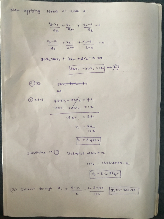
R1 = 100 Ω
R2 = 200 Ω
R3 = 300 Ω
R4 = 200 Ω
R5 = 20 Ω
ξ = 6 V
Connect the circuit shown using the multimeter as the ammeter.
2) Use a voltmeter to measure the potential difference across each resistor. Note which side of each resistor is at higher potential. Use this information to determine the direction of the current flowing in the resistor and mark all current directions in the circuit diagram. Also mark the current flowing through the ammeter.
Disconnect the battery but leave the rest of the circuit intact until you have completed the calculations below.
Analysis and discussion:
1) Redraw the circuit
diagram. Include the directions of all currents.
Homework Answers


Add Answer to:
Part II: Wheatstone Bridge Procedure: 1) Before connecting the circuit, use the multi...
eold and silver are replaced with yellow and grly Part Five: Circuit Analysis 5.3 Extension 8:...
 eold and silver are replaced with yellow and grly Part Five: Circuit Analysis 5.3 Extension 8: Voltages and Current 1. Three resistors, 20 Ω,40 Ω, and 80 Ω are connected in series with a 9.0 v Color-code and construct an electric potential diagram. battery. /2,)Three resistors, 20 Ω, 40 Ω, and 80 Ω are connected in series with a 90V Dileer batery a) Which resistor will have the greatest voltage across it? b) Which resistor, if any, will have the...
!? Verify Kirchhoff’s Current law (I) in = (I) out for junction point “X” in the...
 !? Verify Kirchhoff’s Current law (I) in = (I) out for
junction point “X” in the circuit
point 560 Ω resistor 1000 Ω resistor 4.5 . 1 |ー オー1 ered battery box1 -T 10000 Ω resistor 17 black 1 Is switch (closed for measurements only) +1 To measure each current, the wire it is flowing through must be "cut" (disconnected) and the ammeter inserted in series. COM Do not place the ammeter across a component, as this may damage the...
!? Verify Kirchhoff’s Current law (I) in = (I) out for
junction point “X” in the circuit
point 560 Ω resistor 1000 Ω resistor 4.5 . 1 |ー オー1 ered battery box1 -T 10000 Ω resistor 17 black 1 Is switch (closed for measurements only) +1 To measure each current, the wire it is flowing through must be "cut" (disconnected) and the ammeter inserted in series. COM Do not place the ammeter across a component, as this may damage the...
Part Five: Circuit Analysis 5 is now closed. Draw the schematic en find the voltage across...
 Part Five: Circuit Analysis 5 is now closed. Draw the schematic en find the voltage across each of the following devices. 6. T he switch in the circuit from question for the circuit, and a) 15 Ω resistor b) 202 resistor c) 5 Ω resistor d) the switch e) the battery f With the switch closed, how much current flows through the batte th Through the 5 Ω resistor? Use your answers from above to color-code the circuit, g) 5....
what is b and c 1. Consider the electric circuit below and find: a) total resistance...
 what is b and c
1. Consider the electric circuit below and find: a) total resistance b) potential difference across the resistor Rs c) indicate by drawing on the circuit diagram where and how would you connect instruments to measure the potential difference AV across resistor Ri, and the current I through Rs Indicate the name of each instrument (A- Ammeter or V-Voltmeter) on it 1-0 3.0 Rs
what is b and c
1. Consider the electric circuit below and find: a) total resistance b) potential difference across the resistor Rs c) indicate by drawing on the circuit diagram where and how would you connect instruments to measure the potential difference AV across resistor Ri, and the current I through Rs Indicate the name of each instrument (A- Ammeter or V-Voltmeter) on it 1-0 3.0 Rs
Draw a circuit diagram for the circuit of (Figure 1). You may want to review (Page...
 Draw a circuit diagram for the circuit of (Figure 1).
You may want to review (Page 728) .
Figure
1 of 1A circuit is shown in the figure. A 12-volt battery is
connected by wires to two resistors and a capacitor. The positive
terminal of the battery is connected to a 50-ohm resistor, and the
negative terminal of the battery is connected to one terminal of a
10-microfarad capacitor. Two wires are connected to the other
terminal of a 50-ohm...
Draw a circuit diagram for the circuit of (Figure 1).
You may want to review (Page 728) .
Figure
1 of 1A circuit is shown in the figure. A 12-volt battery is
connected by wires to two resistors and a capacitor. The positive
terminal of the battery is connected to a 50-ohm resistor, and the
negative terminal of the battery is connected to one terminal of a
10-microfarad capacitor. Two wires are connected to the other
terminal of a 50-ohm...
*Answer to first part is 6.0 Volts 4*1.5V= 6 4 AA cells are connected in series....
 *Answer to first part is 6.0 Volts
4*1.5V= 6
4 AA cells are connected in series. These make a true battery of 49 volts. This voltage is then connected to three resistors. R1-200 Ω R2-200 Ω R3-800 Ω R1 and R2 are wired in series with each other, and that series combination is wired in parallel with R3 Start by drawing a schematic diagram of the circuit, then proceed to the calculations. Give all answers to 2 sigfigs precision. The...
*Answer to first part is 6.0 Volts
4*1.5V= 6
4 AA cells are connected in series. These make a true battery of 49 volts. This voltage is then connected to three resistors. R1-200 Ω R2-200 Ω R3-800 Ω R1 and R2 are wired in series with each other, and that series combination is wired in parallel with R3 Start by drawing a schematic diagram of the circuit, then proceed to the calculations. Give all answers to 2 sigfigs precision. The...
Hello, I only need part D and E. Show all work for those two parts. The resistance of the Ammeter...
 Hello,
I only need part D and E. Show all work for those two parts.
Note: the last question in part (e) asks for the I measured by
ammeter, and actual I1
In the figure below, R1-6.50 Ω and R2-R,-R4-26.0 Ω" The battery has an emf of ε-120 V. R1 Ry a.) How much energy is dissipated by all four resistors in one minute? Inserting a measurement device into a circuit to figure out what it's doing will actually affect...
Hello,
I only need part D and E. Show all work for those two parts.
Note: the last question in part (e) asks for the I measured by
ammeter, and actual I1
In the figure below, R1-6.50 Ω and R2-R,-R4-26.0 Ω" The battery has an emf of ε-120 V. R1 Ry a.) How much energy is dissipated by all four resistors in one minute? Inserting a measurement device into a circuit to figure out what it's doing will actually affect...
HOMEWORK FOR LAB 7 KIRCHHOFF'S CIRCUIT RULES Find the equivalent resistance of the followine etwock. Alles...
 HOMEWORK FOR LAB 7 KIRCHHOFF'S CIRCUIT RULES Find the equivalent resistance of the followine etwock. Alles in ohms.) Show your work below. 1. network (All resistances are potential 2. Show on the circuit diagram in Question 1 how you would connect a mu meter to measure the current through the 8-n resistor a. Explain why the multimeter is connected in this way. has a low vesitity so it would difference. b. What characteristic of a good multimeter allows you to...
Example 4. How long must a 1 μΑ current flow to charge a 1 μF capacitor...
 Example 4. How long must a 1 μΑ current flow to charge a 1 μF capacitor to 20 volts? 1 x 10⁻⁶ F = (1 x 10⁻⁶ coulomb sec.1 T sec)/ (20 V). Example 5. A 12-volt battery is connected to a light bulb that is to be used as a light source in a spectrophotometer. The current flowing though the circuit is found to be 0.5 amperes. What is the resistance of the light bulb (represented as a resistor...
Mini-Prj 2. Extraction of Thevenin and Norton Equivalent Circuits by LTspice Part A. Wheatstone B...
 Mini-Prj 2. Extraction of Thevenin and Norton Equivalent Circuits by LTspice Part A. Wheatstone Bridge Circuit with a Voltage Source Vs R5 R1 R2 Vs RL R3 R4 For the circuit as shown below, given that R1= 9 Ω, R2= 17 Ω, R3= 9 Ω' R,-18 Ω, R5= 19 Ω , RL= 2 Ω ,V,-74 V I. Wheatstone Bridge Circuit Analysis (a) Determining the load voltage Vi-Vab for the Wheatstone bridge circuit with LTspice Submit Answer Tries 0/3 (b) Determining...
 eold and silver are replaced with yellow and grly Part Five: Circuit Analysis 5.3 Extension 8: Voltages and Current 1. Three resistors, 20 Ω,40 Ω, and 80 Ω are connected in series with a 9.0 v Color-code and construct an electric potential diagram. battery. /2,)Three resistors, 20 Ω, 40 Ω, and 80 Ω are connected in series with a 90V Dileer batery a) Which resistor will have the greatest voltage across it? b) Which resistor, if any, will have the...
 !? Verify Kirchhoff’s Current law (I) in = (I) out for
junction point “X” in the circuit
point 560 Ω resistor 1000 Ω resistor 4.5 . 1 |ー オー1 ered battery box1 -T 10000 Ω resistor 17 black 1 Is switch (closed for measurements only) +1 To measure each current, the wire it is flowing through must be "cut" (disconnected) and the ammeter inserted in series. COM Do not place the ammeter across a component, as this may damage the...
!? Verify Kirchhoff’s Current law (I) in = (I) out for
junction point “X” in the circuit
point 560 Ω resistor 1000 Ω resistor 4.5 . 1 |ー オー1 ered battery box1 -T 10000 Ω resistor 17 black 1 Is switch (closed for measurements only) +1 To measure each current, the wire it is flowing through must be "cut" (disconnected) and the ammeter inserted in series. COM Do not place the ammeter across a component, as this may damage the...
 Part Five: Circuit Analysis 5 is now closed. Draw the schematic en find the voltage across each of the following devices. 6. T he switch in the circuit from question for the circuit, and a) 15 Ω resistor b) 202 resistor c) 5 Ω resistor d) the switch e) the battery f With the switch closed, how much current flows through the batte th Through the 5 Ω resistor? Use your answers from above to color-code the circuit, g) 5....
 what is b and c
1. Consider the electric circuit below and find: a) total resistance b) potential difference across the resistor Rs c) indicate by drawing on the circuit diagram where and how would you connect instruments to measure the potential difference AV across resistor Ri, and the current I through Rs Indicate the name of each instrument (A- Ammeter or V-Voltmeter) on it 1-0 3.0 Rs
what is b and c
1. Consider the electric circuit below and find: a) total resistance b) potential difference across the resistor Rs c) indicate by drawing on the circuit diagram where and how would you connect instruments to measure the potential difference AV across resistor Ri, and the current I through Rs Indicate the name of each instrument (A- Ammeter or V-Voltmeter) on it 1-0 3.0 Rs
 Draw a circuit diagram for the circuit of (Figure 1).
You may want to review (Page 728) .
Figure
1 of 1A circuit is shown in the figure. A 12-volt battery is
connected by wires to two resistors and a capacitor. The positive
terminal of the battery is connected to a 50-ohm resistor, and the
negative terminal of the battery is connected to one terminal of a
10-microfarad capacitor. Two wires are connected to the other
terminal of a 50-ohm...
Draw a circuit diagram for the circuit of (Figure 1).
You may want to review (Page 728) .
Figure
1 of 1A circuit is shown in the figure. A 12-volt battery is
connected by wires to two resistors and a capacitor. The positive
terminal of the battery is connected to a 50-ohm resistor, and the
negative terminal of the battery is connected to one terminal of a
10-microfarad capacitor. Two wires are connected to the other
terminal of a 50-ohm...
 *Answer to first part is 6.0 Volts
4*1.5V= 6
4 AA cells are connected in series. These make a true battery of 49 volts. This voltage is then connected to three resistors. R1-200 Ω R2-200 Ω R3-800 Ω R1 and R2 are wired in series with each other, and that series combination is wired in parallel with R3 Start by drawing a schematic diagram of the circuit, then proceed to the calculations. Give all answers to 2 sigfigs precision. The...
*Answer to first part is 6.0 Volts
4*1.5V= 6
4 AA cells are connected in series. These make a true battery of 49 volts. This voltage is then connected to three resistors. R1-200 Ω R2-200 Ω R3-800 Ω R1 and R2 are wired in series with each other, and that series combination is wired in parallel with R3 Start by drawing a schematic diagram of the circuit, then proceed to the calculations. Give all answers to 2 sigfigs precision. The...
 Hello,
I only need part D and E. Show all work for those two parts.
Note: the last question in part (e) asks for the I measured by
ammeter, and actual I1
In the figure below, R1-6.50 Ω and R2-R,-R4-26.0 Ω" The battery has an emf of ε-120 V. R1 Ry a.) How much energy is dissipated by all four resistors in one minute? Inserting a measurement device into a circuit to figure out what it's doing will actually affect...
Hello,
I only need part D and E. Show all work for those two parts.
Note: the last question in part (e) asks for the I measured by
ammeter, and actual I1
In the figure below, R1-6.50 Ω and R2-R,-R4-26.0 Ω" The battery has an emf of ε-120 V. R1 Ry a.) How much energy is dissipated by all four resistors in one minute? Inserting a measurement device into a circuit to figure out what it's doing will actually affect...
 HOMEWORK FOR LAB 7 KIRCHHOFF'S CIRCUIT RULES Find the equivalent resistance of the followine etwock. Alles in ohms.) Show your work below. 1. network (All resistances are potential 2. Show on the circuit diagram in Question 1 how you would connect a mu meter to measure the current through the 8-n resistor a. Explain why the multimeter is connected in this way. has a low vesitity so it would difference. b. What characteristic of a good multimeter allows you to...
 Example 4. How long must a 1 μΑ current flow to charge a 1 μF capacitor to 20 volts? 1 x 10⁻⁶ F = (1 x 10⁻⁶ coulomb sec.1 T sec)/ (20 V). Example 5. A 12-volt battery is connected to a light bulb that is to be used as a light source in a spectrophotometer. The current flowing though the circuit is found to be 0.5 amperes. What is the resistance of the light bulb (represented as a resistor...
 Mini-Prj 2. Extraction of Thevenin and Norton Equivalent Circuits by LTspice Part A. Wheatstone Bridge Circuit with a Voltage Source Vs R5 R1 R2 Vs RL R3 R4 For the circuit as shown below, given that R1= 9 Ω, R2= 17 Ω, R3= 9 Ω' R,-18 Ω, R5= 19 Ω , RL= 2 Ω ,V,-74 V I. Wheatstone Bridge Circuit Analysis (a) Determining the load voltage Vi-Vab for the Wheatstone bridge circuit with LTspice Submit Answer Tries 0/3 (b) Determining...
Most questions answered within 3 hours.
-
An short-seller in Tesla is worried the latest management
earnings forecast is too aggressive and the...
asked 38 minutes ago -
Question 3 (1 point)
Fill in the blank. Speed Car Rental company found that the tire...
asked 37 minutes ago -
1. A copper wire is 26.61 cm long and weighs 1.265 g. The
density of copper...
asked 15 minutes ago -
Remember that a concept sketch consists of a sketch (or
series of sketches), labels, and complete...
asked 17 minutes ago -
on a newly discovered planet, the period of a pendulum with a
length of 2 m...
asked 20 minutes ago -
Why [M(CN)6] is not organometallic even it has metal
to carbon bond too
asked 26 minutes ago -
mstar electric has a bond issue outstanding that has a 20 year
life, a $1,000 par...
asked 33 minutes ago -
This is a Business Writing Question:
Common Types of Faulty Sentence Logic:
A. Mixed constructions
B....
asked 34 minutes ago -
Skinner asserts that science, and the common view of science, has
been tarnished. Explain his evidence...
asked 37 minutes ago -
A grocery store's receipts show that Sunday customer purchases
have a skewed distribution with a mean...
asked 43 minutes ago -
A 0.035 mol sample of a weak acid, HA, is dissolved in 437 mL of
water...
asked 55 minutes ago -
a sample of Ar gas has a volume of 6.30 L with an unknown
pressure. the...
asked 56 minutes ago