


desired for RB to have the largest possible value while meeting the other constraints. (a) Determine the values of RB and RE.
+15 V Figure 7
Homework Answers


Add Answer to:
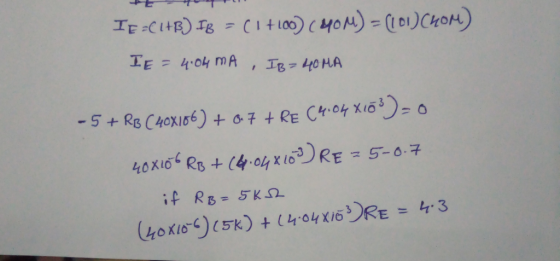
8. Consider the circuit shown in Figure 7. A Q-point value for Ic between a minimum of 4 mA and a maximum of 5 mA is required. Assume that resistor values are constant and that B ranges from 100 to...
Consider the circuit shown in Figure 1. A Q-point value for IC between a minimum of 4 mA and a maximum of 5 mA is required. Assume that resistor values are constant and that β ranges from 100 to 300....
 Consider the circuit shown in Figure 1. A Q-point value for IC
between a minimum of 4 mA and a maximum of 5 mA is required. Assume
that resistor values are constant and that β ranges from 100 to
300. It is desired for RB to have the largest possible value while
meeting the other constraints.
(a) Determine the values of RB and RE.
(b) Explain the contribution of resistor RE for thermal
stabilisation of this circuit (Thermal stabilisation -...
Consider the circuit shown in Figure 1. A Q-point value for IC
between a minimum of 4 mA and a maximum of 5 mA is required. Assume
that resistor values are constant and that β ranges from 100 to
300. It is desired for RB to have the largest possible value while
meeting the other constraints.
(a) Determine the values of RB and RE.
(b) Explain the contribution of resistor RE for thermal
stabilisation of this circuit (Thermal stabilisation -...
can anyone help with c? 8. Consider the circuit shown in Figure 7. A Q-point value for Ic between a minimum of 4 mA and a maximum of 5 mA is required. Assume that resistor values are constant and tha...
 can anyone help with c?
8. Consider the circuit shown in Figure 7. A Q-point value for Ic between a minimum of 4 mA and a maximum of 5 mA is required. Assume that resistor values are constant and that B ranges from 100 to 300. It is desired for RB to have the largest possible value while meeting the othei constraints. (a) Determine the values of RB and RE. (b) Explain the contribution of resistor Re for thermal stabilisation...
can anyone help with c?
8. Consider the circuit shown in Figure 7. A Q-point value for Ic between a minimum of 4 mA and a maximum of 5 mA is required. Assume that resistor values are constant and that B ranges from 100 to 300. It is desired for RB to have the largest possible value while meeting the othei constraints. (a) Determine the values of RB and RE. (b) Explain the contribution of resistor Re for thermal stabilisation...
Please do not answer if you are going to copy the answers of others. Only do...
 Please do not answer if you are going to copy the answers of
others. Only do it if you know how. The others are wrong.
8. Consider the circuit shown in Figure A Q-point value for Ic between a minimum of 4 mA and a maximum of 5 mA is required. Assume that resistor values are constant and that ranges from 100 to 300. It is We were unable to transcribe this image
Please do not answer if you are going to copy the answers of
others. Only do it if you know how. The others are wrong.
8. Consider the circuit shown in Figure A Q-point value for Ic between a minimum of 4 mA and a maximum of 5 mA is required. Assume that resistor values are constant and that ranges from 100 to 300. It is We were unable to transcribe this image
#4 The accompanying circuit shows a 4-resistor biased JFET transistor Determine the values of Rp and Rs so that the Q-point is equal to, VDsq 10 V and IDg 5 mA . For the JFET take IDss = 10 mA...
 #4
The accompanying circuit shows a 4-resistor biased JFET transistor Determine the values of Rp and Rs so that the Q-point is equal to, VDsq 10 V and IDg 5 mA . For the JFET take IDss = 10 mA, VP =-5 V and λ 0 . The circuit parameters are, R1-740 k, R2-22 1.85 ka, Rs-85 ㏀ and RL-3.5 ㏀. Take the power supply VDD 24 V 2- Vo R1 Vi R2 Signal generator 4-In reference to the circuit...
#4
The accompanying circuit shows a 4-resistor biased JFET transistor Determine the values of Rp and Rs so that the Q-point is equal to, VDsq 10 V and IDg 5 mA . For the JFET take IDss = 10 mA, VP =-5 V and λ 0 . The circuit parameters are, R1-740 k, R2-22 1.85 ka, Rs-85 ㏀ and RL-3.5 ㏀. Take the power supply VDD 24 V 2- Vo R1 Vi R2 Signal generator 4-In reference to the circuit...
Download the datasheet for 2N3904 and find the value of Bp. (Hint: Use average value) Be=...
 Download the datasheet for 2N3904 and find the value of Bp. (Hint: Use average value) Be= Voc +10 V RB We are going to consider the common emitter configuration circuit shown in the figure to test a 2N3904 npn Bipolar Junction Transistor (BJT) under DC bias conditions. Your circuit should place a fixed collector resistor, Rc, in the circuit to prevent the collector current, Ic, from exceeding 40 mA (for this, you know that the minimum value of is zero)....
D 6.112 The MOSFET in the circuit of Fig. P6.112 has = 5 mA/V, and V, = 40 V. (a) Find the values of Rs,RD, and RG so that ID=0.4 mA, the largest possible value for R is used while a maximum sig...
 D 6.112 The MOSFET in the circuit of Fig. P6.112 has = 5 mA/V, and V, = 40 V. (a) Find the values of Rs,RD, and RG so that ID=0.4 mA, the largest possible value for R is used while a maximum signal swing at the drain of +0.8 V is possible, and the input resistance at the gate is 10 MS2. Neglect the Early effect. (b) Find the values of gm and r, at the bias point. (c) If...
URGENT The NMOS in the shown figure has Vt = 0.8V, kn = 5 mA/V2, and...
 URGENT
The NMOS in the shown figure has Vt = 0.8V, kn = 5 mA/V2, and VA = 40 V. The circuit also has Vdd = 5V, VSS = -5V, RG = RLD = 1 M2, and RLS = 0 A. [3 marks] Neglecting the channel length modulation effect, find the value of Rs so that the NMOS operates in saturation with Ip = 0.4 mA B. [2 marks] Neglecting the channel length modulation effect, find the largest possible value...
URGENT
The NMOS in the shown figure has Vt = 0.8V, kn = 5 mA/V2, and VA = 40 V. The circuit also has Vdd = 5V, VSS = -5V, RG = RLD = 1 M2, and RLS = 0 A. [3 marks] Neglecting the channel length modulation effect, find the value of Rs so that the NMOS operates in saturation with Ip = 0.4 mA B. [2 marks] Neglecting the channel length modulation effect, find the largest possible value...
4. The MOSFET in the circuit given below has Vi- 1 V, kn 0.8 mA/V2, and VA 40 V a) Find the values of Rs, Ro, and Ro so that Io -0.1 mA, the largest possible value for RD is used while a maximum...
 4. The MOSFET in the circuit given below has Vi- 1 V, kn 0.8 mA/V2, and VA 40 V a) Find the values of Rs, Ro, and Ro so that Io -0.1 mA, the largest possible value for RD is used while a maximum signal swing at the drain of tl V is possible, and the input resistance at the gate is 10 MS2. b) Find the values of gm and ro at the bias point c) If terminal Z...
5. (20 points) For the amplifier in the following figure: +Vcc Rout Rc C3 R2 Rin Ri 1 k R3 Vo Vi R1 RE -VEE a) Draw the de equivalent circuit and find the Q-point. Assume B -75 b) Draw the equiv...
 5. (20 points) For the amplifier in the following figure: +Vcc Rout Rc C3 R2 Rin Ri 1 k R3 Vo Vi R1 RE -VEE a) Draw the de equivalent circuit and find the Q-point. Assume B -75 b) Draw the equivalent circuit used for ac analysis. Find the values in Thevenin equivalent representation for the amplifiers between C, and C as shown below. What is the maximum value of v, that satisfies the small- signal assumption? Rout Ri vi...
Problem 7 Re Consider the circuit shown in (Figure 1). Suppose that va = 130 cos...
 Problem 7 Re Consider the circuit shown in (Figure 1). Suppose that va = 130 cos 10,000+ V, where is in seconds. Part A Determine the load impedance for the circuit that will result in maximum average power being transferred to the load. Express your answer in ohms to three significant figures. Enter your answer in rectangular form. View Available Hints) 21 = 20.0 20.00 22 Previous Answers Correct Here we learn how to find the impedance of the circuit...
 Consider the circuit shown in Figure 1. A Q-point value for IC
between a minimum of 4 mA and a maximum of 5 mA is required. Assume
that resistor values are constant and that β ranges from 100 to
300. It is desired for RB to have the largest possible value while
meeting the other constraints.
(a) Determine the values of RB and RE.
(b) Explain the contribution of resistor RE for thermal
stabilisation of this circuit (Thermal stabilisation -...
Consider the circuit shown in Figure 1. A Q-point value for IC
between a minimum of 4 mA and a maximum of 5 mA is required. Assume
that resistor values are constant and that β ranges from 100 to
300. It is desired for RB to have the largest possible value while
meeting the other constraints.
(a) Determine the values of RB and RE.
(b) Explain the contribution of resistor RE for thermal
stabilisation of this circuit (Thermal stabilisation -...
 can anyone help with c?
8. Consider the circuit shown in Figure 7. A Q-point value for Ic between a minimum of 4 mA and a maximum of 5 mA is required. Assume that resistor values are constant and that B ranges from 100 to 300. It is desired for RB to have the largest possible value while meeting the othei constraints. (a) Determine the values of RB and RE. (b) Explain the contribution of resistor Re for thermal stabilisation...
can anyone help with c?
8. Consider the circuit shown in Figure 7. A Q-point value for Ic between a minimum of 4 mA and a maximum of 5 mA is required. Assume that resistor values are constant and that B ranges from 100 to 300. It is desired for RB to have the largest possible value while meeting the othei constraints. (a) Determine the values of RB and RE. (b) Explain the contribution of resistor Re for thermal stabilisation...
 Please do not answer if you are going to copy the answers of
others. Only do it if you know how. The others are wrong.
8. Consider the circuit shown in Figure A Q-point value for Ic between a minimum of 4 mA and a maximum of 5 mA is required. Assume that resistor values are constant and that ranges from 100 to 300. It is We were unable to transcribe this image
Please do not answer if you are going to copy the answers of
others. Only do it if you know how. The others are wrong.
8. Consider the circuit shown in Figure A Q-point value for Ic between a minimum of 4 mA and a maximum of 5 mA is required. Assume that resistor values are constant and that ranges from 100 to 300. It is We were unable to transcribe this image
 #4
The accompanying circuit shows a 4-resistor biased JFET transistor Determine the values of Rp and Rs so that the Q-point is equal to, VDsq 10 V and IDg 5 mA . For the JFET take IDss = 10 mA, VP =-5 V and λ 0 . The circuit parameters are, R1-740 k, R2-22 1.85 ka, Rs-85 ㏀ and RL-3.5 ㏀. Take the power supply VDD 24 V 2- Vo R1 Vi R2 Signal generator 4-In reference to the circuit...
#4
The accompanying circuit shows a 4-resistor biased JFET transistor Determine the values of Rp and Rs so that the Q-point is equal to, VDsq 10 V and IDg 5 mA . For the JFET take IDss = 10 mA, VP =-5 V and λ 0 . The circuit parameters are, R1-740 k, R2-22 1.85 ka, Rs-85 ㏀ and RL-3.5 ㏀. Take the power supply VDD 24 V 2- Vo R1 Vi R2 Signal generator 4-In reference to the circuit...
 Download the datasheet for 2N3904 and find the value of Bp. (Hint: Use average value) Be= Voc +10 V RB We are going to consider the common emitter configuration circuit shown in the figure to test a 2N3904 npn Bipolar Junction Transistor (BJT) under DC bias conditions. Your circuit should place a fixed collector resistor, Rc, in the circuit to prevent the collector current, Ic, from exceeding 40 mA (for this, you know that the minimum value of is zero)....
 D 6.112 The MOSFET in the circuit of Fig. P6.112 has = 5 mA/V, and V, = 40 V. (a) Find the values of Rs,RD, and RG so that ID=0.4 mA, the largest possible value for R is used while a maximum signal swing at the drain of +0.8 V is possible, and the input resistance at the gate is 10 MS2. Neglect the Early effect. (b) Find the values of gm and r, at the bias point. (c) If...
 URGENT
The NMOS in the shown figure has Vt = 0.8V, kn = 5 mA/V2, and VA = 40 V. The circuit also has Vdd = 5V, VSS = -5V, RG = RLD = 1 M2, and RLS = 0 A. [3 marks] Neglecting the channel length modulation effect, find the value of Rs so that the NMOS operates in saturation with Ip = 0.4 mA B. [2 marks] Neglecting the channel length modulation effect, find the largest possible value...
URGENT
The NMOS in the shown figure has Vt = 0.8V, kn = 5 mA/V2, and VA = 40 V. The circuit also has Vdd = 5V, VSS = -5V, RG = RLD = 1 M2, and RLS = 0 A. [3 marks] Neglecting the channel length modulation effect, find the value of Rs so that the NMOS operates in saturation with Ip = 0.4 mA B. [2 marks] Neglecting the channel length modulation effect, find the largest possible value...
 4. The MOSFET in the circuit given below has Vi- 1 V, kn 0.8 mA/V2, and VA 40 V a) Find the values of Rs, Ro, and Ro so that Io -0.1 mA, the largest possible value for RD is used while a maximum signal swing at the drain of tl V is possible, and the input resistance at the gate is 10 MS2. b) Find the values of gm and ro at the bias point c) If terminal Z...
 5. (20 points) For the amplifier in the following figure: +Vcc Rout Rc C3 R2 Rin Ri 1 k R3 Vo Vi R1 RE -VEE a) Draw the de equivalent circuit and find the Q-point. Assume B -75 b) Draw the equivalent circuit used for ac analysis. Find the values in Thevenin equivalent representation for the amplifiers between C, and C as shown below. What is the maximum value of v, that satisfies the small- signal assumption? Rout Ri vi...
 Problem 7 Re Consider the circuit shown in (Figure 1). Suppose that va = 130 cos 10,000+ V, where is in seconds. Part A Determine the load impedance for the circuit that will result in maximum average power being transferred to the load. Express your answer in ohms to three significant figures. Enter your answer in rectangular form. View Available Hints) 21 = 20.0 20.00 22 Previous Answers Correct Here we learn how to find the impedance of the circuit...
Most questions answered within 3 hours.
-
Why would natural selection not minimize costs (in the form of
symptoms) of evolved defenses? (choose...
asked 3 minutes ago -
What is true about a critical task?
Latest finish time - latest start time = 0...
asked 5 minutes ago -
A company uses a
process costing system. Its Assembly Department's beginning
inventory consisted of 56,800 units,...
asked 5 minutes ago -
a
sealed glass cylinder contains 325 g of N2 gas at 1.02 atm at 20 c....
asked 9 minutes ago -
The main difference between an equity and a nonequity alliance
is that
A
equity alliances are...
asked 8 minutes ago -
Need help with this, in JAVA, using netbeans. A
complete response will receive a positive comment...
asked 16 minutes ago -
An imprest petty cash fund of $600 was established for minor
disbursements. At the end of...
asked 21 minutes ago -
Sharpe Cutter is a small company that produces specialty knives
for paper cutting machinery. The annual...
asked 26 minutes ago -
Calculating the Ka of a weak acid from
pH:
The pH of a 0.68M solution of...
asked 27 minutes ago -
1.What process is pushing back against gravity in the very
center (the core) of sun-like stars?...
asked 47 minutes ago -
This question is from the textbook "Python for ArcGIS" by Laura
Tateosian:
Write a script "triangles.py"...
asked 45 minutes ago -
Which of the following is an impediment that makes it
difficult for firms to achieve the...
asked 46 minutes ago