
Homework Answers

Add Answer to:
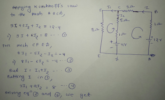
Determint the curvent in ealh branun uf the ciruit shown in fiqurt 3 2 -WL- 5...
5. Four capacitors Ci = 1 uF, C2 = 2 uF, Cz = 3 uF, and...
 5. Four capacitors Ci = 1 uF, C2 = 2 uF, Cz = 3 uF, and CA = 4 uF are connected to a 12 V battery as shown in figure below. Lola 12 V Find (a) the capacitance between the points A and B, (b) the total charge in the circuit, (c) the charge on each capacitor, and (d) the potential on each capacitor. oo and
+4V PMOS (WL)2-8 -0.03 V-1 NMOS: (WL)s-2 =0.02 V-1 Re 50 Ω Consider the circuit shown...
 +4V PMOS (WL)2-8 -0.03 V-1 NMOS: (WL)s-2 =0.02 V-1 Re 50 Ω Consider the circuit shown above, determine (a) the open circuit voltage gain (i.e. open circuit the 50 Ω load resistor and determine Vout/Vin) and (b) If V,,-10 my, what value of Vout occurs across the 50 Ω load resistor. You may consider RG to be large enough to ignore for the small signal trekl.
helppppp pleaseeee Ri= 2 k12 C1 = 2 uF R2 = 3 k12 C2 = 3...
 helppppp pleaseeee
Ri= 2 k12 C1 = 2 uF R2 = 3 k12 C2 = 3 uF V = 120 V a. What is the time constant for the circuit? (5 points) b. Determine the charges on each capacitor as functions of time after the switch is closed (20 points) 4 (15 points) A PHY 112 student wires a circuit as shown below: 222 5Ω 12 V 32 SV T Find the current through all three resistors.
helppppp pleaseeee
Ri= 2 k12 C1 = 2 uF R2 = 3 k12 C2 = 3 uF V = 120 V a. What is the time constant for the circuit? (5 points) b. Determine the charges on each capacitor as functions of time after the switch is closed (20 points) 4 (15 points) A PHY 112 student wires a circuit as shown below: 222 5Ω 12 V 32 SV T Find the current through all three resistors.
s uie 4) a) Find the equivalent capacitance for the circuit given, where, Ces uf C2-2...
 s uie 4) a) Find the equivalent capacitance for the circuit given, where, Ces uf C2-2 uF,Cs-3 HF. b) Determine the charge on each capacitor and the voltage across each, assuming the battery voltage is V-4v. C2 C1 b C3
Find the equivalent capacitance for the circuit shown. 6 F 3 UF 1 UF Ceg- UF
 Find the equivalent capacitance for the circuit shown. 6 F 3 UF 1 UF Ceg- UF
12. The ideal op-amp circuit is shown in Figure. Find , and, respectively 2012 30k V+...
 12. The ideal op-amp circuit is shown in Figure. Find , and, respectively 2012 30k V+ + Vo un V. 10ko | + 4V 12. The ideal op-amp circuit is shown in Figure. Find V+ ,V_ and vo, respectively. 2022 Vo 30k 2 V+ w V. w 10k2 4V
15 F 5 F 8 UF 20 uF HHI HHH 40 V 4 25 UF F...
 15 F 5 F 8 UF 20 uF HHI HHH 40 V 4 25 UF F 12 F 10 UF A. Find the equivalent capacitance of the circuit. B. What is the charge stored by the 5 uF capacitor? C. What is the voltage across the 12 uF capacitor? D. What is the energy stored by the 10 uF capacitor?
1.0 uF 2.0 uF Consider the combination of capacitors shown in the diagram at right. Calculate...
 1.0 uF 2.0 uF Consider the combination of capacitors shown in the diagram at right. Calculate the equivalent capacitance, and the voltage across each capacitor when the combination is connected to a 15 V battery. [2 marks] 1.0 uF
hysics 113 Worksheet 2 Spring 2019 Problem 2 470 nF 33 nF 2.2 uF 4.7 uF...
 hysics 113 Worksheet 2 Spring 2019 Problem 2 470 nF 33 nF 2.2 uF 4.7 uF 3.3 uF 2 Figure 1: Capacitor Network Define AV VB VA 10 V and calculate the following: (3 Points) Calculate the Equivalent Capacitance, Cq, of the circuit shown in Figure 1. . (3 Points) Calculate the Charge on the Equivalent Capacitance, (3 Points) Calculate the Voltage at PointJ in Figure 1 with respect to Terminal B Problem3 Assume
12: Question 10. - 10.0 pts possible Consider the capacitor circuit shown below. 144 uF 144...
 12: Question 10. - 10.0 pts possible Consider the capacitor circuit shown below. 144 uF 144 uF 72 uF b 72 uF O 1. 36 2. 50.6667 a 3. 12.6667 EB 4. 16 5. 48 Determine the equivalent capacitance for the combination shown. Answer in units of uF. 6. 51.3333 O 7. 60 8. 42 O 9. 14 0 10. 36.6667
 5. Four capacitors Ci = 1 uF, C2 = 2 uF, Cz = 3 uF, and CA = 4 uF are connected to a 12 V battery as shown in figure below. Lola 12 V Find (a) the capacitance between the points A and B, (b) the total charge in the circuit, (c) the charge on each capacitor, and (d) the potential on each capacitor. oo and
 +4V PMOS (WL)2-8 -0.03 V-1 NMOS: (WL)s-2 =0.02 V-1 Re 50 Ω Consider the circuit shown above, determine (a) the open circuit voltage gain (i.e. open circuit the 50 Ω load resistor and determine Vout/Vin) and (b) If V,,-10 my, what value of Vout occurs across the 50 Ω load resistor. You may consider RG to be large enough to ignore for the small signal trekl.
 helppppp pleaseeee
Ri= 2 k12 C1 = 2 uF R2 = 3 k12 C2 = 3 uF V = 120 V a. What is the time constant for the circuit? (5 points) b. Determine the charges on each capacitor as functions of time after the switch is closed (20 points) 4 (15 points) A PHY 112 student wires a circuit as shown below: 222 5Ω 12 V 32 SV T Find the current through all three resistors.
helppppp pleaseeee
Ri= 2 k12 C1 = 2 uF R2 = 3 k12 C2 = 3 uF V = 120 V a. What is the time constant for the circuit? (5 points) b. Determine the charges on each capacitor as functions of time after the switch is closed (20 points) 4 (15 points) A PHY 112 student wires a circuit as shown below: 222 5Ω 12 V 32 SV T Find the current through all three resistors.
 s uie 4) a) Find the equivalent capacitance for the circuit given, where, Ces uf C2-2 uF,Cs-3 HF. b) Determine the charge on each capacitor and the voltage across each, assuming the battery voltage is V-4v. C2 C1 b C3
 Find the equivalent capacitance for the circuit shown. 6 F 3 UF 1 UF Ceg- UF
 12. The ideal op-amp circuit is shown in Figure. Find , and, respectively 2012 30k V+ + Vo un V. 10ko | + 4V 12. The ideal op-amp circuit is shown in Figure. Find V+ ,V_ and vo, respectively. 2022 Vo 30k 2 V+ w V. w 10k2 4V
 15 F 5 F 8 UF 20 uF HHI HHH 40 V 4 25 UF F 12 F 10 UF A. Find the equivalent capacitance of the circuit. B. What is the charge stored by the 5 uF capacitor? C. What is the voltage across the 12 uF capacitor? D. What is the energy stored by the 10 uF capacitor?
 1.0 uF 2.0 uF Consider the combination of capacitors shown in the diagram at right. Calculate the equivalent capacitance, and the voltage across each capacitor when the combination is connected to a 15 V battery. [2 marks] 1.0 uF
 hysics 113 Worksheet 2 Spring 2019 Problem 2 470 nF 33 nF 2.2 uF 4.7 uF 3.3 uF 2 Figure 1: Capacitor Network Define AV VB VA 10 V and calculate the following: (3 Points) Calculate the Equivalent Capacitance, Cq, of the circuit shown in Figure 1. . (3 Points) Calculate the Charge on the Equivalent Capacitance, (3 Points) Calculate the Voltage at PointJ in Figure 1 with respect to Terminal B Problem3 Assume
 12: Question 10. - 10.0 pts possible Consider the capacitor circuit shown below. 144 uF 144 uF 72 uF b 72 uF O 1. 36 2. 50.6667 a 3. 12.6667 EB 4. 16 5. 48 Determine the equivalent capacitance for the combination shown. Answer in units of uF. 6. 51.3333 O 7. 60 8. 42 O 9. 14 0 10. 36.6667
Most questions answered within 3 hours.
-
The extent to which assets are financed by borrowed funds and
other liabilities is indicated by:...
asked 6 minutes ago -
Explain in detail
Germany is the fifth largest economy
explain what goods and services Germany specializes...
asked 20 minutes ago -
The density of platinum is 21.45 g/mL. If a cube of platinum
with a mass of...
asked 26 minutes ago -
Accounts Receivable
Sales
A/R Posting
Extended Sales Invoice
Packing Slip
Compare invoice to packing slip 2...
asked 28 minutes ago -
Michaella, age 23, is a full-time law student and is claimed by
her parents as a...
asked 29 minutes ago -
Why are polymers not typically casted into products?
asked 46 minutes ago -
When rolling a die 129 times, what is the probability of rolling
a 6 no more...
asked 1 hour ago -
4. A call option currently sells for $7.75. It has a strike
price of $85 and...
asked 52 minutes ago -
1.
You need to prepare 10.0 liters of an acid aqueous solution with a
pH of...
asked 54 minutes ago -
Along an aggregate supply curve, if the level of output is less
than the natural level...
asked 55 minutes ago -
By 2025, annual consumption in emerging markets will total $30
trillion and contribute more than ________...
asked 1 hour ago -
At what point does reformation cease to be a viable option for
those who are oppressed...
asked 1 hour ago