
Homework Answers

Add Answer to:
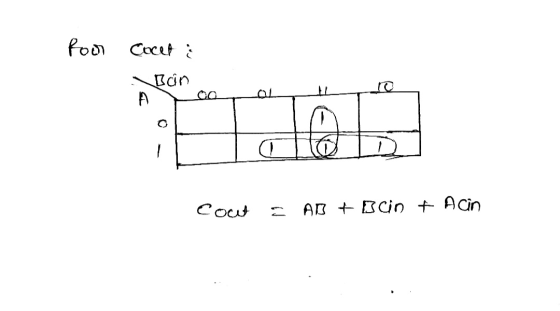
3) А B Cin- —S Cout Create the truth table fort he given digital circuit. Afterthat...
a full-adder circuit is used to add 2 bits A and B and the carry (Cin)...
a full-adder circuit is used to add 2 bits A and B and the carry (Cin) that resulted from the addition of the previous 2 bits. It then produces a SUM S and a carry out (Cout) that would be added to the more significant bits. Generate a truth table that has inputs A, B and Cin and the 2 outputs S and Cout. Find the logical function from the truth table and simplify it, if possible. Implement the function...
digital fundamentals thomas floyd Q8. A) Write the SOP (Minterm) Boolean expression for the truth table...
 digital fundamentals thomas floyd
Q8. A) Write the SOP (Minterm) Boolean expression for the truth table in Fig 2 below and draw the logic circuit that will perform the logic in the truth table in. B) Finally implement the same logic circuit by universal gates. [2+2=4] Inputs Output Inputs Output с в А Y C B A Y 0 0 0 0 0 0 0 0 0 1 0 0 1 0 0 0 1 1 1 0 1 1...
digital fundamentals thomas floyd
Q8. A) Write the SOP (Minterm) Boolean expression for the truth table in Fig 2 below and draw the logic circuit that will perform the logic in the truth table in. B) Finally implement the same logic circuit by universal gates. [2+2=4] Inputs Output Inputs Output с в А Y C B A Y 0 0 0 0 0 0 0 0 0 1 0 0 1 0 0 0 1 1 1 0 1 1...
1. There are two circuits in the following Truth Table (each is part of a Full...
1. There are two circuits in the following Truth Table (each is part of a Full Adder). Using Karnaugh Maps produce the circuit for Sum (S) given the inputs A, B, and Cin. A) Show the Karnaugh Map. B) Show the circuit. A B Cin SUM(S) Cout 0 0 0 0 0 0 0 1 1 0 0 1 0 1 0 0 1 1 0 1 1 0 0 1 0 1 0 1 0 1 1 1 0...
a) fill in truth table for A and read the number from top to bottom as...
 a) fill in truth table for A and read the number from
top to bottom as a binary number and convert to a decimal number
for your answer.
b) fill in truth table for B and read the number from
top to bottom as a binary number and convert to a decimal number
for your answer
c) fill in truth table for C and read the number from
top to bottom as a binary number and convert to a decimal...
a) fill in truth table for A and read the number from
top to bottom as a binary number and convert to a decimal number
for your answer.
b) fill in truth table for B and read the number from
top to bottom as a binary number and convert to a decimal number
for your answer
c) fill in truth table for C and read the number from
top to bottom as a binary number and convert to a decimal...
For Function F(a, b, c) = (a+b)' *c+a*b*c' +a*c Create the truth table Create the combinational...
For Function F(a, b, c) = (a+b)' *c+a*b*c' +a*c Create the truth table Create the combinational circuit implementing the function Reduce the circuit
(iii) The functionality of a digital unit is provided in the following table: S I Cin=0...
 (iii) The functionality of a digital unit is provided in the following table: S I Cin=0 Cin = 1 F = A + B (addition) F= A +1 (increment) F = A -1 (decrement) F=A+B'+1 (subtraction) Derive the MUX inputs lo, 11, 12, and 13 that implement that unit? Ici АНХ FA TIT MUX 4x1 Y; CH1 Show your work:
2. Given push buttons (A and B), coil relays (CR1 and CR2) and LED Light indicator, a) complete the truth table for the following relay logic circuit, and then b) complete a truth table for the...
 2. Given push buttons (A and B), coil relays (CR1 and CR2) and LED Light indicator, a) complete the truth table for the following relay logic circuit, and then b) complete a truth table for the same circuit, but when relay coil 2 failed open: (10pts) し2 CR1 CR2 CR1 CR2 Indicator True Table (Good Circuit) Output True Table (With Fault) B Output 0 0 0 0 1 0 0
2. Given push buttons (A and B), coil relays (CR1...
2. Given push buttons (A and B), coil relays (CR1 and CR2) and LED Light indicator, a) complete the truth table for the following relay logic circuit, and then b) complete a truth table for the same circuit, but when relay coil 2 failed open: (10pts) し2 CR1 CR2 CR1 CR2 Indicator True Table (Good Circuit) Output True Table (With Fault) B Output 0 0 0 0 1 0 0
2. Given push buttons (A and B), coil relays (CR1...
(2) (5 pomis) TL A-011000103, B = 011011012. Clearly 3. Conversion between truth table, circuit diagram...
 (2) (5 pomis) TL A-011000103, B = 011011012. Clearly 3. Conversion between truth table, circuit diagram and Boolean function. (1) (6 points) For the circuit below, write the Boolean expression F(A, B, C). Then write down the truth table for F. (2) (4 points) Draw a circuit schematic diagram which implements the following Boolean function. (Don't simplify the expression.) F(X2, X1, Xo) = x;'(x2+xo)' + xo'X1X2 (3) (10 points) The output of a logic function F(A,B,C) is one only if...
QUESTION 1 Suppose that an engineer wants to create a three bit adder using the method...
 QUESTION 1 Suppose that an engineer wants to create a three bit adder using the method described in Lecture 25. As part of the design process, the engineer creates the following building block component: a b Cin Full Adder Cout s In order to create the three bit adder, each of the three building blocks will need to be correctly connected together. In the circuit below, each of the possible connection points has been labeled with a number: A[2] 2...
A21921 2. +9V Re Vout Re RE CE 0v Figure 3 (a) ) State the purpose of each of the capacitors Cin, Cout and Ce in the circuit [3 shown in Figure 3. (i) Derive an expression for the input resistanc...
 A21921 2. +9V Re Vout Re RE CE 0v Figure 3 (a) ) State the purpose of each of the capacitors Cin, Cout and Ce in the circuit [3 shown in Figure 3. (i) Derive an expression for the input resistance of this circuit in terms of the [5 mutual conductance of the transistor gm and its current gain β. we require an amplifier with a gain of-100, an output impedance of 1kΩ and an input impedance of 1k2. The...
 digital fundamentals thomas floyd
Q8. A) Write the SOP (Minterm) Boolean expression for the truth table in Fig 2 below and draw the logic circuit that will perform the logic in the truth table in. B) Finally implement the same logic circuit by universal gates. [2+2=4] Inputs Output Inputs Output с в А Y C B A Y 0 0 0 0 0 0 0 0 0 1 0 0 1 0 0 0 1 1 1 0 1 1...
digital fundamentals thomas floyd
Q8. A) Write the SOP (Minterm) Boolean expression for the truth table in Fig 2 below and draw the logic circuit that will perform the logic in the truth table in. B) Finally implement the same logic circuit by universal gates. [2+2=4] Inputs Output Inputs Output с в А Y C B A Y 0 0 0 0 0 0 0 0 0 1 0 0 1 0 0 0 1 1 1 0 1 1...
 a) fill in truth table for A and read the number from
top to bottom as a binary number and convert to a decimal number
for your answer.
b) fill in truth table for B and read the number from
top to bottom as a binary number and convert to a decimal number
for your answer
c) fill in truth table for C and read the number from
top to bottom as a binary number and convert to a decimal...
a) fill in truth table for A and read the number from
top to bottom as a binary number and convert to a decimal number
for your answer.
b) fill in truth table for B and read the number from
top to bottom as a binary number and convert to a decimal number
for your answer
c) fill in truth table for C and read the number from
top to bottom as a binary number and convert to a decimal...
 (iii) The functionality of a digital unit is provided in the following table: S I Cin=0 Cin = 1 F = A + B (addition) F= A +1 (increment) F = A -1 (decrement) F=A+B'+1 (subtraction) Derive the MUX inputs lo, 11, 12, and 13 that implement that unit? Ici АНХ FA TIT MUX 4x1 Y; CH1 Show your work:
 2. Given push buttons (A and B), coil relays (CR1 and CR2) and LED Light indicator, a) complete the truth table for the following relay logic circuit, and then b) complete a truth table for the same circuit, but when relay coil 2 failed open: (10pts) し2 CR1 CR2 CR1 CR2 Indicator True Table (Good Circuit) Output True Table (With Fault) B Output 0 0 0 0 1 0 0
2. Given push buttons (A and B), coil relays (CR1...
2. Given push buttons (A and B), coil relays (CR1 and CR2) and LED Light indicator, a) complete the truth table for the following relay logic circuit, and then b) complete a truth table for the same circuit, but when relay coil 2 failed open: (10pts) し2 CR1 CR2 CR1 CR2 Indicator True Table (Good Circuit) Output True Table (With Fault) B Output 0 0 0 0 1 0 0
2. Given push buttons (A and B), coil relays (CR1...
 (2) (5 pomis) TL A-011000103, B = 011011012. Clearly 3. Conversion between truth table, circuit diagram and Boolean function. (1) (6 points) For the circuit below, write the Boolean expression F(A, B, C). Then write down the truth table for F. (2) (4 points) Draw a circuit schematic diagram which implements the following Boolean function. (Don't simplify the expression.) F(X2, X1, Xo) = x;'(x2+xo)' + xo'X1X2 (3) (10 points) The output of a logic function F(A,B,C) is one only if...
 QUESTION 1 Suppose that an engineer wants to create a three bit adder using the method described in Lecture 25. As part of the design process, the engineer creates the following building block component: a b Cin Full Adder Cout s In order to create the three bit adder, each of the three building blocks will need to be correctly connected together. In the circuit below, each of the possible connection points has been labeled with a number: A[2] 2...
 A21921 2. +9V Re Vout Re RE CE 0v Figure 3 (a) ) State the purpose of each of the capacitors Cin, Cout and Ce in the circuit [3 shown in Figure 3. (i) Derive an expression for the input resistance of this circuit in terms of the [5 mutual conductance of the transistor gm and its current gain β. we require an amplifier with a gain of-100, an output impedance of 1kΩ and an input impedance of 1k2. The...
Most questions answered within 3 hours.
-
According to the bureau of labor statisitcs, the average salart
of the 21,340 registered nurses in...
asked 11 minutes ago -
A typical automobile under hard braking loses speed at a rate of
about 7.1 m/s2; the...
asked 7 minutes ago -
please give me clear picture
Section 1: DNS nslookup
The Domain Name System (DNS) translates hostnames...
asked 30 minutes ago -
If you could provide a step by step on how to solve this
problem, I would...
asked 32 minutes ago -
hello. ive been confused on this question and its a toss up between
A & D....
asked 47 minutes ago -
a
tank of motor oil (sg= 0.88) sits in the corner of a body shop,
mounted...
asked 52 minutes ago -
Project 2
Description
Create a Visual C# project that when an employee's biweekly sales
amount is...
asked 1 hour ago -
which of the following statements is false?
A. The realized return is the total return we...
asked 1 hour ago -
what is the corresponding MIPS assembly code for the statements
shown below that written in C....
asked 1 hour ago -
Fresh Price Accounting, Inc., is a well-known accounting firm
that provides exceptional services to businesses and...
asked 1 hour ago -
Hiroshi Sato, an owner of a sushi restaurant in San Francisco,
has been following an aggressive...
asked 1 hour ago -
Part 1-
Calculating the current through the resistor A 59-Ω resistor in
a circuit has a...
asked 1 hour ago