
Homework Answers
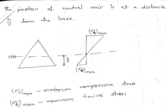
Pure bending is a condition of stress where a bending moment is applied to a beam without the simultaneous presence of axial, shear, or torsional forces. Pure bending occurs only under a constant bending moment (M) since the shear force (V), which is equal tozero. In reality, this state of pure bending does not practically exist, because such a state needs an absolutely weightless member. The state of pure bending is an approximation made to derive formulas.
Add Answer to:
1. Describe the state of pure bending (moment? shear? curvature?) 2. Draw the normal stress profile...
2. Draw Shear Force and Bending Moment Diagram (use your preferred method). Determine Maximum Ten...
 2. Draw Shear Force and Bending Moment Diagram (use your preferred method). Determine Maximum Tensile and Compressive Stresses due to bending, state where on the beam these occur. For the mid-point between A and B, determine shear stress at neutral axis; 2" from the top of the flange; at the junction between web and flange and on the top of the flange for the cross-section. Plot of the bending stress and shear stress distribution diagram across the cross section of...
a. Determine the maximum tensile and compressive bending stresses associated with the maximum positive moment. b. Determine the maximum tensile and compressive bending stresses associated with the ma...
 a. Determine the maximum tensile and compressive bending
stresses associated with the maximum positive moment.b. Determine the maximum tensile and compressive bending
stresses associated with the maximum negative moment.c. Determine the absolute maximum tensile stress in the beam and
the location.d. Determine the absolute maximum compressive stress in the beam
and the location.e. Determine the maximum shear stress associated with maximum
positive shear force.f. Determine the maximum shear stress associated with maximum
negative shear force.g. Determine the absolute maximum shear...
a. Determine the maximum tensile and compressive bending
stresses associated with the maximum positive moment.b. Determine the maximum tensile and compressive bending
stresses associated with the maximum negative moment.c. Determine the absolute maximum tensile stress in the beam and
the location.d. Determine the absolute maximum compressive stress in the beam
and the location.e. Determine the maximum shear stress associated with maximum
positive shear force.f. Determine the maximum shear stress associated with maximum
negative shear force.g. Determine the absolute maximum shear...
a. Determine the reaction forces.
 a. Determine the reaction forces.b. Determine the location of neutral axis with the given geometry.c. Determine the moment of inertia about the neutral axis.d. Draw shear force diagram.e. Draw bending moment diagram.f. Determine the maximum positive and maximum negative shear forces and their locations.g. Determine the maximum positive and maximum negative bending moments and their locations.h. Determine the maximum tensile and compressive bending stresses associated with the maximum positive moment.i. Determine the maximum tensile and compressive bending stresses associated with...
Problem 1: Draw the shear force and bending moment diagram for the beam shown below. (10)...
 Problem 1: Draw the shear force and bending moment diagram for the beam shown below. (10) Estimate the maximum bending stress located at section C (shown below). (10) Clearly identify the location on the cross section where the maximum bending stress is located. Is it tensile or compressive? Explain your answer.
6. Determine the maximum positive and maximum negative shear forces and their locations.
 6. Determine the maximum positive and maximum negative shear forces and their locations. 7. Determine the maximum positive and maximum negative bending moments and their locations 8. Determine the maximum tensile and compressive bending stresses associated with the maximum positive moment 9. Determine the maximum tensile and compressive bending stresses associated with the maximum negative moment 10. Determine the absolute maximum tensile stress in the beam and the location. 11. Determine the absolute maximum compressive stress in the beam and the location 12. Determine the maximum...
(a) Sketch the shear force and bending moment diagram for the beam shown. Indicate the values and locations of maximum shear and moment.
 (a) Sketch the shear force and bending moment diagram for the beam shown. Indicate the values and locations of maximum shear and moment. (b) With the beam cross section shown, determine the maximum tensile stress, maximum compressive stress, and maximum transverse shear stress in the beam.
3. The beam, with symmetric cross-section about y (all thicknesses of 1 in) as shown, is...
 3. The beam, with symmetric cross-section about y (all thicknesses of 1 in) as shown, is subjected to an internal moment of M 480 kip.in and a shear force of V 340 kip. For this system, a) determine the location of the neutral axis, y (measured from the bottom of cross-section as shown) and the area moment of inertia, I about the neutral axis (NA or z-axis), the maximum compressive, (o,nax), and tensile, (Omax): normal stresses, and b) o kip....
2013 Michael Swanbom 08 O Cross Section Dimensions 106 cm 25 cm 32 mm 33 mm Problem Statement A c...
 2013 Michael Swanbom 08 O Cross Section Dimensions 106 cm 25 cm 32 mm 33 mm Problem Statement A cantilever beam has a cross-section shaped as a sector of a circle. It is supported at A and loaded with a concentrated load of F 870 N and a concentrated moment of M = 361 N*m. The dimensions of the beam are given in the table above. Find the normal stresses at points D, E, and G in the cross-section, at...
Blem 2. (70 points) 1. For the beam shown in Figure (a): a) b) draw the shear force and bending m...
 blem 2. (70 points) 1. For the beam shown in Figure (a): a) b) draw the shear force and bending moment diagrams. (30 points) Select the most economical W shape for the beam with an allowable bending stress of 30 ksi. (10 points) determine the maximum tensile and compressive bending stresses at any location along the beam if the section shown in Figure (b) is used instead of the W shape section selectedin Part b. Would the beam be safe...
A beam whose cross-section is shown in the figure is subjected to a bending moment M...
 A beam whose cross-section is shown in the figure is subjected to a bending moment M inclined at 0 = 70° from the z axis. a) Locate the orientation of the neutral axis B and draw this axis on the figure b) Calculate the maximum flexural tensile stress Omax,T and the maximum flexural compressive stress Omax.c in the beam and indicate at which points in the section these occur. M= 2 Nm D e Z 20 mm A B 60...
 2. Draw Shear Force and Bending Moment Diagram (use your preferred method). Determine Maximum Tensile and Compressive Stresses due to bending, state where on the beam these occur. For the mid-point between A and B, determine shear stress at neutral axis; 2" from the top of the flange; at the junction between web and flange and on the top of the flange for the cross-section. Plot of the bending stress and shear stress distribution diagram across the cross section of...
 a. Determine the maximum tensile and compressive bending
stresses associated with the maximum positive moment.b. Determine the maximum tensile and compressive bending
stresses associated with the maximum negative moment.c. Determine the absolute maximum tensile stress in the beam and
the location.d. Determine the absolute maximum compressive stress in the beam
and the location.e. Determine the maximum shear stress associated with maximum
positive shear force.f. Determine the maximum shear stress associated with maximum
negative shear force.g. Determine the absolute maximum shear...
a. Determine the maximum tensile and compressive bending
stresses associated with the maximum positive moment.b. Determine the maximum tensile and compressive bending
stresses associated with the maximum negative moment.c. Determine the absolute maximum tensile stress in the beam and
the location.d. Determine the absolute maximum compressive stress in the beam
and the location.e. Determine the maximum shear stress associated with maximum
positive shear force.f. Determine the maximum shear stress associated with maximum
negative shear force.g. Determine the absolute maximum shear...
 a. Determine the reaction forces.b. Determine the location of neutral axis with the given geometry.c. Determine the moment of inertia about the neutral axis.d. Draw shear force diagram.e. Draw bending moment diagram.f. Determine the maximum positive and maximum negative shear forces and their locations.g. Determine the maximum positive and maximum negative bending moments and their locations.h. Determine the maximum tensile and compressive bending stresses associated with the maximum positive moment.i. Determine the maximum tensile and compressive bending stresses associated with...
 Problem 1: Draw the shear force and bending moment diagram for the beam shown below. (10) Estimate the maximum bending stress located at section C (shown below). (10) Clearly identify the location on the cross section where the maximum bending stress is located. Is it tensile or compressive? Explain your answer.
 3. The beam, with symmetric cross-section about y (all thicknesses of 1 in) as shown, is subjected to an internal moment of M 480 kip.in and a shear force of V 340 kip. For this system, a) determine the location of the neutral axis, y (measured from the bottom of cross-section as shown) and the area moment of inertia, I about the neutral axis (NA or z-axis), the maximum compressive, (o,nax), and tensile, (Omax): normal stresses, and b) o kip....
 2013 Michael Swanbom 08 O Cross Section Dimensions 106 cm 25 cm 32 mm 33 mm Problem Statement A cantilever beam has a cross-section shaped as a sector of a circle. It is supported at A and loaded with a concentrated load of F 870 N and a concentrated moment of M = 361 N*m. The dimensions of the beam are given in the table above. Find the normal stresses at points D, E, and G in the cross-section, at...
 blem 2. (70 points) 1. For the beam shown in Figure (a): a) b) draw the shear force and bending moment diagrams. (30 points) Select the most economical W shape for the beam with an allowable bending stress of 30 ksi. (10 points) determine the maximum tensile and compressive bending stresses at any location along the beam if the section shown in Figure (b) is used instead of the W shape section selectedin Part b. Would the beam be safe...
 A beam whose cross-section is shown in the figure is subjected to a bending moment M inclined at 0 = 70° from the z axis. a) Locate the orientation of the neutral axis B and draw this axis on the figure b) Calculate the maximum flexural tensile stress Omax,T and the maximum flexural compressive stress Omax.c in the beam and indicate at which points in the section these occur. M= 2 Nm D e Z 20 mm A B 60...
Most questions answered within 3 hours.
-
The extent to which assets are financed by borrowed funds and
other liabilities is indicated by:...
asked 44 minutes ago -
Explain in detail
Germany is the fifth largest economy
explain what goods and services Germany specializes...
asked 59 minutes ago -
The density of platinum is 21.45 g/mL. If a cube of platinum
with a mass of...
asked 1 hour ago -
Accounts Receivable
Sales
A/R Posting
Extended Sales Invoice
Packing Slip
Compare invoice to packing slip 2...
asked 1 hour ago -
Michaella, age 23, is a full-time law student and is claimed by
her parents as a...
asked 1 hour ago -
Why are polymers not typically casted into products?
asked 1 hour ago -
When rolling a die 129 times, what is the probability of rolling
a 6 no more...
asked 1 hour ago -
4. A call option currently sells for $7.75. It has a strike
price of $85 and...
asked 1 hour ago -
1.
You need to prepare 10.0 liters of an acid aqueous solution with a
pH of...
asked 1 hour ago -
Along an aggregate supply curve, if the level of output is less
than the natural level...
asked 1 hour ago -
By 2025, annual consumption in emerging markets will total $30
trillion and contribute more than ________...
asked 1 hour ago -
At what point does reformation cease to be a viable option for
those who are oppressed...
asked 1 hour ago