

b) using the values of the capacitor, inductance and
resistance, calculate the valies of the circuit peak to peak
currents and write them down in the table.
c) insert the resistance Rs as indicated in previous sections, to
allow the current measurement of the source. measure the value of
the peak to peak voltage Vrs and the resulting current and insert
the values in tje table.
d) determine the peak to peak value of the IL and IC currents
e) calculate the peak to peak value of the IR current using the
fact that VR=E.
help me please!!!
Homework Answers
Here I am going to explain everything on the paper only.


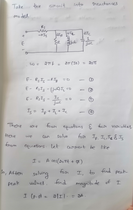


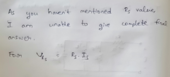
Here the only thing I used is Kirchoff's Voltage Law. As there no RS value mentioned, I am unable to give you a clear final answer. But I hope the process that I gave will help you in finding the answers.
I hope the whole discussion and my handwriting are understandable. I hope this will be useful to you.
Thanking You
Add Answer to:
b) using the values of the capacitor, inductance and
resistance, calculate the valies of the circuit...
PROCEDU Part 1 Resistance (a) Construct the circuit of Fig. 4.1. Insert the measured values of...
 PROCEDU Part 1 Resistance (a) Construct the circuit of Fig. 4.1. Insert the measured values of the counter if available mined by the ohmmeter section of your multimeter. Hook up the frequeney Red r measured / 100Ω Sensing resistor Red measured 500 Hz Oscilloscope Black Black FIG. 4.1 Caution: Always ensure that the ground of the oscilloscope is connected to the ground of the oscillator. Otherwise a hazardous situation may result (b) Set the voltage across R to 4 V...
TITLE: SERIES PARALLEL CIRCUITSI OBJECTIVE: To verify current, voltage, and resistance relati parallel circuit. ance relationships...
 TITLE: SERIES PARALLEL CIRCUITSI OBJECTIVE: To verify current, voltage, and resistance relati parallel circuit. ance relationships in a series- PRELIMINARY: Before beginning the experiment, each student solution for the circuits of FIG.1 and FIG. 2. The student should solve voltage and current that the experiment asks him to measure. student must submit a detailed Puld solve for every value of EQUIPMENT: Feedback Kit DC Ammeter, AD R = 10002 R = 680 2 Rs = 4702 R. = 8202 R....
Review Part A. Find the relationship between the phasor voltage and phasor current for a resistance...
 Review Part A. Find the relationship between the phasor voltage and phasor current for a resistance The resistor shown here has been transformed into the phasor domain: Ik 4k Suppose that the phasor current is given by IR = 752120 mA. Find the phasor voltage VR. Enter a complex number in polar form, with phase angle in degrees. View Available Hint(s) 3002120 V Submit Previous Answers Correct Part B - Draw the phasor diagram of the resistance from Part A...
Help fill in table The CH2 waveform vr(t) is shown in red. 3. Now, double the...
 Help fill in table
The CH2 waveform vr(t) is shown in red. 3. Now, double the function generator frequency (to f=1250Hz about 1250Hz) to display exactly two complete cycles in 8 horizontal divisions. Do not change the amplitude of e(t). Again, both waveforms should be centered vertically on the scope grid. Adjust the vertical POSITION knobs if necessary. Carefully sketch and label both waveforms on the grid. Use the same settings (VOLTS/DIV AND SEC/DIV from part A4.) as with the...
Help fill in table
The CH2 waveform vr(t) is shown in red. 3. Now, double the function generator frequency (to f=1250Hz about 1250Hz) to display exactly two complete cycles in 8 horizontal divisions. Do not change the amplitude of e(t). Again, both waveforms should be centered vertically on the scope grid. Adjust the vertical POSITION knobs if necessary. Carefully sketch and label both waveforms on the grid. Use the same settings (VOLTS/DIV AND SEC/DIV from part A4.) as with the...
Course and Section cto EXPERIMENT ac series-Parallel Sinusoidal Circuits OBJECTIVES 1. Measure th...
 Course and Section cto EXPERIMENT ac series-Parallel Sinusoidal Circuits OBJECTIVES 1. Measure the currents of series-parallel R-L and R-C networks using sensing resistors 2. Demonstrate the Pythagorean relationship between the currents of the networks. 3. Measure the phase angles associated with the currents of the networks. 4. Calculate the input impedance of a parallel network using measured values EQUIPMENT REQUIRED Instruments Resistors 1-10-Q, 470-Ω, l-kM (14.W) Inductors 1-10-mH Capacitors 1-0.02-pF I-DMM 1--Oscilloscope 1-Audio oscillator or function generator 1--Frequency counter (if...
PHYS 212 RECITATION EXERCISE 1: USING PHASORS FOR A DRIVEN RC CIRCUIT We will consider a...
 PHYS 212 RECITATION EXERCISE 1: USING PHASORS FOR A DRIVEN RC CIRCUIT We will consider a circuit consisting of a time varying emf in series with a capacitor and resistor. The capacitance and resistance are fixed but we can tune the frequency of the source. In an AC circuit, each element has a "reactance" which can be used to relate the peak current through the element to the peak voltage across the element 1. What does the angular frequency of...
I NEED HELP WITH QUESTION #5 PLEASE AND CAN SOME FILL OUT THE FIRST ROW OF...
 I NEED HELP WITH QUESTION #5 PLEASE AND CAN SOME FILL OUT THE
FIRST ROW OF MY TABLE FOR 10Hz. I DONT KNOW HOW TO DO IT SO IF SOME
CAN FILL OUT THE FIRST TABLE AND SHOW ME HOW, THEN I CAN FINISH THE
REST. THANK YOU.
Reset Run / STOP 2uF Simulation Speed Current Speed 0 Power Brightness Current Circuit: 10Hz 1k New X S -15.933 V 100.165 ms 167.681 V capacitor, 2 UF 21.071 V resistor, 1...
I NEED HELP WITH QUESTION #5 PLEASE AND CAN SOME FILL OUT THE
FIRST ROW OF MY TABLE FOR 10Hz. I DONT KNOW HOW TO DO IT SO IF SOME
CAN FILL OUT THE FIRST TABLE AND SHOW ME HOW, THEN I CAN FINISH THE
REST. THANK YOU.
Reset Run / STOP 2uF Simulation Speed Current Speed 0 Power Brightness Current Circuit: 10Hz 1k New X S -15.933 V 100.165 ms 167.681 V capacitor, 2 UF 21.071 V resistor, 1...
EXERCISE 2: USING PHASORS FOR A DRIVEN RC CIRCUIT 10. On the middle set of axes,...
 EXERCISE 2: USING PHASORS FOR A DRIVEN RC CIRCUIT 10. On the middle set of axes, draw phasors for k and ε using the provided ve phasor as a basis for a circuit in which R- 2Xc. Start by deciding what the peak voltage across the capacitor must be compared to the peak voltage across the resistor and then draw the appropriate Vc phasor We will consider a circuit consisting of a time varying emf in series with a capacitor...
I need a help with my lab, I write all data that get. 355 SERIES SINUSOIDAL...
 I need a help with my lab, I write all data that get.
355 SERIES SINUSOIDAL CIRCU CUITS neeseed 000 10 mH 10 kHz + R E-8V(Pp) V 1 kn Channel 2 Vert: 1 Vidiv Hor: 20 us/div. Channel 1 Vert: 1 Vidiv Hor: 20 us/div. FIG. 9.1 (b) After setting E to 8 V (p-p), determine the peak-to-peak voltage for Ve from chan- nel 2 and record in the top row of Table 9.1 Determine the phase angle 8,...
I need a help with my lab, I write all data that get.
355 SERIES SINUSOIDAL CIRCU CUITS neeseed 000 10 mH 10 kHz + R E-8V(Pp) V 1 kn Channel 2 Vert: 1 Vidiv Hor: 20 us/div. Channel 1 Vert: 1 Vidiv Hor: 20 us/div. FIG. 9.1 (b) After setting E to 8 V (p-p), determine the peak-to-peak voltage for Ve from chan- nel 2 and record in the top row of Table 9.1 Determine the phase angle 8,...
Problems,,,,,
 1 2
+
–
i(t)
C R
L
iT i(t)
iD
+
–
L C R
1. Analysis and design of a buck-boost converter: A buck-boost converter is illustrated in Fig. 1(a),
and a practical implementation using a transistor and diode is shown in Fig. 1(b).
+
(a)
Vg
v
Figure 1 Buck–boost converter
of Problem 1: (a) ideal converter
circuit, (b) implementation using
MOSFET and diode.
–
Q1
D1
(b) +
Vg
v
Page 2
iL
(t) + vL...
1 2
+
–
i(t)
C R
L
iT i(t)
iD
+
–
L C R
1. Analysis and design of a buck-boost converter: A buck-boost converter is illustrated in Fig. 1(a),
and a practical implementation using a transistor and diode is shown in Fig. 1(b).
+
(a)
Vg
v
Figure 1 Buck–boost converter
of Problem 1: (a) ideal converter
circuit, (b) implementation using
MOSFET and diode.
–
Q1
D1
(b) +
Vg
v
Page 2
iL
(t) + vL...
 PROCEDU Part 1 Resistance (a) Construct the circuit of Fig. 4.1. Insert the measured values of the counter if available mined by the ohmmeter section of your multimeter. Hook up the frequeney Red r measured / 100Ω Sensing resistor Red measured 500 Hz Oscilloscope Black Black FIG. 4.1 Caution: Always ensure that the ground of the oscilloscope is connected to the ground of the oscillator. Otherwise a hazardous situation may result (b) Set the voltage across R to 4 V...
 TITLE: SERIES PARALLEL CIRCUITSI OBJECTIVE: To verify current, voltage, and resistance relati parallel circuit. ance relationships in a series- PRELIMINARY: Before beginning the experiment, each student solution for the circuits of FIG.1 and FIG. 2. The student should solve voltage and current that the experiment asks him to measure. student must submit a detailed Puld solve for every value of EQUIPMENT: Feedback Kit DC Ammeter, AD R = 10002 R = 680 2 Rs = 4702 R. = 8202 R....
 Review Part A. Find the relationship between the phasor voltage and phasor current for a resistance The resistor shown here has been transformed into the phasor domain: Ik 4k Suppose that the phasor current is given by IR = 752120 mA. Find the phasor voltage VR. Enter a complex number in polar form, with phase angle in degrees. View Available Hint(s) 3002120 V Submit Previous Answers Correct Part B - Draw the phasor diagram of the resistance from Part A...
 Help fill in table
The CH2 waveform vr(t) is shown in red. 3. Now, double the function generator frequency (to f=1250Hz about 1250Hz) to display exactly two complete cycles in 8 horizontal divisions. Do not change the amplitude of e(t). Again, both waveforms should be centered vertically on the scope grid. Adjust the vertical POSITION knobs if necessary. Carefully sketch and label both waveforms on the grid. Use the same settings (VOLTS/DIV AND SEC/DIV from part A4.) as with the...
Help fill in table
The CH2 waveform vr(t) is shown in red. 3. Now, double the function generator frequency (to f=1250Hz about 1250Hz) to display exactly two complete cycles in 8 horizontal divisions. Do not change the amplitude of e(t). Again, both waveforms should be centered vertically on the scope grid. Adjust the vertical POSITION knobs if necessary. Carefully sketch and label both waveforms on the grid. Use the same settings (VOLTS/DIV AND SEC/DIV from part A4.) as with the...
 Course and Section cto EXPERIMENT ac series-Parallel Sinusoidal Circuits OBJECTIVES 1. Measure the currents of series-parallel R-L and R-C networks using sensing resistors 2. Demonstrate the Pythagorean relationship between the currents of the networks. 3. Measure the phase angles associated with the currents of the networks. 4. Calculate the input impedance of a parallel network using measured values EQUIPMENT REQUIRED Instruments Resistors 1-10-Q, 470-Ω, l-kM (14.W) Inductors 1-10-mH Capacitors 1-0.02-pF I-DMM 1--Oscilloscope 1-Audio oscillator or function generator 1--Frequency counter (if...
 PHYS 212 RECITATION EXERCISE 1: USING PHASORS FOR A DRIVEN RC CIRCUIT We will consider a circuit consisting of a time varying emf in series with a capacitor and resistor. The capacitance and resistance are fixed but we can tune the frequency of the source. In an AC circuit, each element has a "reactance" which can be used to relate the peak current through the element to the peak voltage across the element 1. What does the angular frequency of...
 I NEED HELP WITH QUESTION #5 PLEASE AND CAN SOME FILL OUT THE
FIRST ROW OF MY TABLE FOR 10Hz. I DONT KNOW HOW TO DO IT SO IF SOME
CAN FILL OUT THE FIRST TABLE AND SHOW ME HOW, THEN I CAN FINISH THE
REST. THANK YOU.
Reset Run / STOP 2uF Simulation Speed Current Speed 0 Power Brightness Current Circuit: 10Hz 1k New X S -15.933 V 100.165 ms 167.681 V capacitor, 2 UF 21.071 V resistor, 1...
I NEED HELP WITH QUESTION #5 PLEASE AND CAN SOME FILL OUT THE
FIRST ROW OF MY TABLE FOR 10Hz. I DONT KNOW HOW TO DO IT SO IF SOME
CAN FILL OUT THE FIRST TABLE AND SHOW ME HOW, THEN I CAN FINISH THE
REST. THANK YOU.
Reset Run / STOP 2uF Simulation Speed Current Speed 0 Power Brightness Current Circuit: 10Hz 1k New X S -15.933 V 100.165 ms 167.681 V capacitor, 2 UF 21.071 V resistor, 1...
 EXERCISE 2: USING PHASORS FOR A DRIVEN RC CIRCUIT 10. On the middle set of axes, draw phasors for k and ε using the provided ve phasor as a basis for a circuit in which R- 2Xc. Start by deciding what the peak voltage across the capacitor must be compared to the peak voltage across the resistor and then draw the appropriate Vc phasor We will consider a circuit consisting of a time varying emf in series with a capacitor...
 I need a help with my lab, I write all data that get.
355 SERIES SINUSOIDAL CIRCU CUITS neeseed 000 10 mH 10 kHz + R E-8V(Pp) V 1 kn Channel 2 Vert: 1 Vidiv Hor: 20 us/div. Channel 1 Vert: 1 Vidiv Hor: 20 us/div. FIG. 9.1 (b) After setting E to 8 V (p-p), determine the peak-to-peak voltage for Ve from chan- nel 2 and record in the top row of Table 9.1 Determine the phase angle 8,...
I need a help with my lab, I write all data that get.
355 SERIES SINUSOIDAL CIRCU CUITS neeseed 000 10 mH 10 kHz + R E-8V(Pp) V 1 kn Channel 2 Vert: 1 Vidiv Hor: 20 us/div. Channel 1 Vert: 1 Vidiv Hor: 20 us/div. FIG. 9.1 (b) After setting E to 8 V (p-p), determine the peak-to-peak voltage for Ve from chan- nel 2 and record in the top row of Table 9.1 Determine the phase angle 8,...
Most questions answered within 3 hours.
-
What mechanisms Drive speciation??
(I.e. what was Dawins theory on the orgin of species, and how...
asked 7 minutes ago -
The manager at a car assembly plant believes that the mean
assembly time for a car...
asked 58 minutes ago -
Which of the following is true of electron capture?
A) It decreases the nuclide's mass number...
asked 2 hours ago -
Assuming an efficiency of 43.10%, calculate the actual yield of
magnesium nitrate formed from 114.9 g...
asked 3 hours ago -
The highly pathogenic bacterium Clostridium
perfringens causes gangrene, a disease that results in the
destruction of...
asked 4 hours ago -
In the context of situation analysis, which of the following is
a category for analysis in...
asked 4 hours ago -
In a study of the gas phase decomposition of sulfuryl chloride
at 600 K SO2Cl2(g)SO2(g) +...
asked 4 hours ago -
75 g of 2-propanol (C3H8O) and 25 g of pentane are mixed in a
200 mL...
asked 4 hours ago -
The 2800-turn coil in a dc motor has an area per turn of 1.1 ×
10-2...
asked 5 hours ago -
Draw a combinational logic circuit diagram with a symbol inside
the box for two I/P of...
asked 5 hours ago -
The cliché we use quite a lot in finance is: there is a need to
maximize...
asked 5 hours ago -
In class we discussed the addition of HCl to alpha pinene. Would
you expect one or...
asked 5 hours ago