
Homework Answers

Add Answer to:
Help fill in table
The CH2 waveform vr(t) is shown in red. 3. Now, double the...
1. Consider the single-phase VSI inverter shown below dc VR(t) iz(t) a) If your input voltage Vdc...
 1. Consider the single-phase VSI inverter shown below dc VR(t) iz(t) a) If your input voltage Vdc - 100V2 V and switching frequency is 60 Hz with zero delay angle. Then, sketch the square wave output. Mark the peak values [10 marks] b) Sketch the fundamental output on the top of the above waveform. Mark the peak value По marksl c) The above A VSI is used to create a square wave output with 100v2 V at 60 Hz. This...
Problems 1 through 8 refer to the sinusoidal waveforms on the right, which are displayed on...
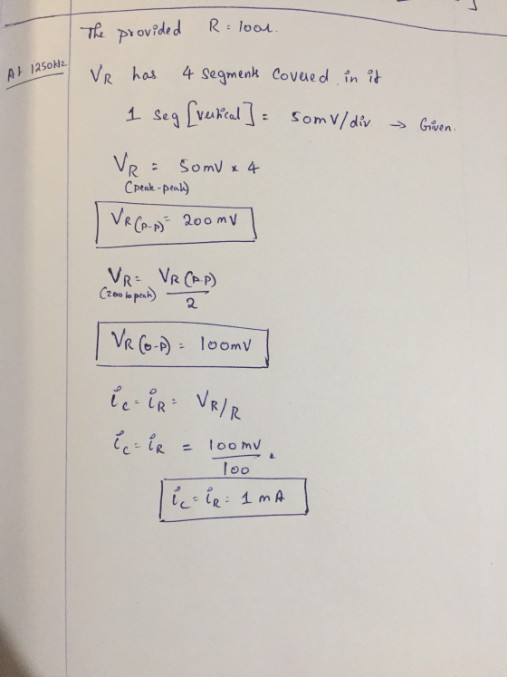
 Problems 1 through 8 refer to the sinusoidal waveforms on the right, which are displayed on an oscilloscope having the following settings: Channel 1 Vertical Axis: 1 V/Division Channel 2 Vertical Axis: 50 mV/Division Horizontal Axis: 1 ms/Division The zero-volt level is at the center of the screen for both channels. Consider the left edge of the screen to be the t=0 axis. Consider the waveform displayed on Channel 1 as the output voltage of a function generator. In ze...
NI ELVISmx Basic Settings Advanced Settings Sample Rate: 200.00iS Oane10 Settings Channel 1 Settings Source AI 1 At 0 Enabled Probe Scale Volts,01, Poston pv) 100 mV 200 mV Trigger Type Sope Level M...
 NI ELVISmx Basic Settings Advanced Settings Sample Rate: 200.00iS Oane10 Settings Channel 1 Settings Source AI 1 At 0 Enabled Probe Scale Volts,01, Poston pv) 100 mV 200 mV Trigger Type Sope Level M Horizontal positon (%) 50 200 us T: 250.00 umeout Ci: 489.99 C284.13 mV CHO Meas RMS:345.95 mV Freq: 999.998 Hz Vpp: 979.42 m CH1 Meas: RMS: 59.46 mV Freq: 999.928 Hz pp: 168.31 m Instrument Control Acquiation Mode Print Log Help Autoscale Cursors OnCi CHO Fig....
Ctri Question 3 (20 Marks) Lab 1-Zener Circuits and Applications Theory: Zener diode is designed ...
 Ctri Question 3 (20 Marks) Lab 1-Zener Circuits and Applications Theory: Zener diode is designed to operate in reverse conduction. Zener breakdown occurs at a precisely defined voltage, allowing the diode to be used as a voltage reference or clipper. While Zener diodes are usually operated in reverse conduction, they may also be operated in cutoff and forward conduction. There are two different effects that are used in "Zener diodes". The only practical difference is that the two types have...
I am currently trying to figure out the experiment below. Please complete Table 1 with an...
 I am currently trying to figure out the experiment below. Please
complete Table 1 with an explanation, I appreciate it thank
you! Promise to give thumbs up!
Introduction The phase differences between the output voltage, the voltage across the inductor, the voltage across the capacitor, and the voltage across the resistor will be examined at resonant frequency. The voltage and phase relationship will also be examined for frequencies above and below resonance. Theory An inductor, a capacitor, and a resistor are...
I am currently trying to figure out the experiment below. Please
complete Table 1 with an explanation, I appreciate it thank
you! Promise to give thumbs up!
Introduction The phase differences between the output voltage, the voltage across the inductor, the voltage across the capacitor, and the voltage across the resistor will be examined at resonant frequency. The voltage and phase relationship will also be examined for frequencies above and below resonance. Theory An inductor, a capacitor, and a resistor are...
 1. Consider the single-phase VSI inverter shown below dc VR(t) iz(t) a) If your input voltage Vdc - 100V2 V and switching frequency is 60 Hz with zero delay angle. Then, sketch the square wave output. Mark the peak values [10 marks] b) Sketch the fundamental output on the top of the above waveform. Mark the peak value По marksl c) The above A VSI is used to create a square wave output with 100v2 V at 60 Hz. This...
 Problems 1 through 8 refer to the sinusoidal waveforms on the right, which are displayed on an oscilloscope having the following settings: Channel 1 Vertical Axis: 1 V/Division Channel 2 Vertical Axis: 50 mV/Division Horizontal Axis: 1 ms/Division The zero-volt level is at the center of the screen for both channels. Consider the left edge of the screen to be the t=0 axis. Consider the waveform displayed on Channel 1 as the output voltage of a function generator. In ze...
 NI ELVISmx Basic Settings Advanced Settings Sample Rate: 200.00iS Oane10 Settings Channel 1 Settings Source AI 1 At 0 Enabled Probe Scale Volts,01, Poston pv) 100 mV 200 mV Trigger Type Sope Level M Horizontal positon (%) 50 200 us T: 250.00 umeout Ci: 489.99 C284.13 mV CHO Meas RMS:345.95 mV Freq: 999.998 Hz Vpp: 979.42 m CH1 Meas: RMS: 59.46 mV Freq: 999.928 Hz pp: 168.31 m Instrument Control Acquiation Mode Print Log Help Autoscale Cursors OnCi CHO Fig....
 Ctri Question 3 (20 Marks) Lab 1-Zener Circuits and Applications Theory: Zener diode is designed to operate in reverse conduction. Zener breakdown occurs at a precisely defined voltage, allowing the diode to be used as a voltage reference or clipper. While Zener diodes are usually operated in reverse conduction, they may also be operated in cutoff and forward conduction. There are two different effects that are used in "Zener diodes". The only practical difference is that the two types have...
 I am currently trying to figure out the experiment below. Please
complete Table 1 with an explanation, I appreciate it thank
you! Promise to give thumbs up!
Introduction The phase differences between the output voltage, the voltage across the inductor, the voltage across the capacitor, and the voltage across the resistor will be examined at resonant frequency. The voltage and phase relationship will also be examined for frequencies above and below resonance. Theory An inductor, a capacitor, and a resistor are...
I am currently trying to figure out the experiment below. Please
complete Table 1 with an explanation, I appreciate it thank
you! Promise to give thumbs up!
Introduction The phase differences between the output voltage, the voltage across the inductor, the voltage across the capacitor, and the voltage across the resistor will be examined at resonant frequency. The voltage and phase relationship will also be examined for frequencies above and below resonance. Theory An inductor, a capacitor, and a resistor are...
Most questions answered within 3 hours.
-
Rod figures that it takes an average (mean) of =20 minutes with
a standard deviation of...
asked 1 minute from now -
You have 5 ul of a pure (undiluted) culture at a concentration
of 3.6 x 10⁶...
asked 3 minutes ago -
______ activity indicates the presence of an electron transport
chain.
1- gelatinase 2- oxidase 3- caseinase...
asked 5 minutes ago -
The molarity of a silver nitrate solution is 0.192 M. How many
grams of silver ions...
asked 18 minutes ago -
Which of the following solutes will produce a greater increase
in boiling point when it is...
asked 14 minutes ago -
true or false: Series connected electrical circuit is a voltage
divider, and voltage of each device...
asked 9 minutes ago -
A 100-W lightbulb has a resistance of about 12 Ω when cold (20
∘C) and 128...
asked 13 minutes ago -
For the asset shown in the following table, use the capital
asset pricing model to find...
asked 14 minutes ago -
If the impulse response of a circuit is a pulse y(t) = u(t) –
u(t-T), T...
asked 21 minutes ago -
Eukaryotic cells have __ which is similar to prokaryotes of
Archaea.
A Ester-linked membrane lipids
B...
asked 30 minutes ago -
true or false. If work is done on a system by it's
surroundings, its value is...
asked 34 minutes ago -
Rene Descartes establishes a dualist approach to the world.
Explain this dualism, and how it connects...
asked 41 minutes ago