(From Mitra M7.5.) (using matlab)Design a digital Chebyshev-I lowpass filter operating at a sampling rate of...
(From Mitra M7.5.) (using matlab)Design a digital Chebyshev-I
lowpass filter operating at a sampling rate of 80 kHz with a
passband edge frequency at 4 kHz, a passband ripple of 0.5 dB, and
a minimum stopband attenuation of 45 dB at 20 kHz using the
bilinear transformation method. Determine the order of the analog
prototype using the command cheb1ord and then design the analog
prototype using cheb1ap. Transform the analog filter into a digital
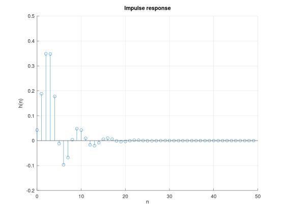
one using the bilinear command. Plot the frequency response,
pole-zero diagram and impulse response of the digital filter. Show
the steps of the design procedure.
Homework Answers
MATLAB:
clc;clear all;close all;
%Design of digital Chebyshev-I lowpass filter
%specifications
Rp=0.5; Rs=45;fp=4000; Fs=80000;fs=20000;
%Nomalized frequencies
Wp=2*fp/Fs;Ws=2*fs/Fs;
%Find order of the filter and cutoff frequency
[N,Wp] = cheb1ord(Wp,Ws,Rp,Rs)
[z,p,k] = cheb1ap(N,Rp);
[num,den] = zp2tf(z,p,k);
%Bilinear transformation to get digital transfer function
[b,a]=bilinear(num,den,1)
figure;%plot frequency response
freqz(b,a,1024,Fs)
figure;%plot pole zero plot
zplane(b,a)
figure;%Impulse response
N=50;n=0:1:N-1;
h=impz(b,a,N)
stem(n,h);grid;
xlabel('n')
ylabel('h(n)')
title('Impulse response')
Plot:


Add Answer to:
(From Mitra M7.5.) (using matlab)Design a digital Chebyshev-I
lowpass filter operating at a sampling rate of...
2. Design a digital lowpass filter to meet the following specifications: passband edge = 0.45π stopband...
2. Design a digital lowpass filter to meet the following specifications: passband edge = 0.45π stopband edge = 0.5π Rp = 0.5 dB, As = 60 dB a. Design a Buttterworth filter, you may use the butterord and butter commands to implement. b. Design Chebyshev Type 1 filter ( use the equivalent commands to above ) c. Design an Elliptic fitler ( use the equivalent commands to part a ). d. List the order of each filter and find the...
An IIR low-pass filter is to be designed to meet the following specifications:
An IIR low-pass filter is to be designed to meet the following specifications: 1. Passband cutoff frequency of 0.22 π with a passband ripple less than 0.01.2. Stopband cutoff frequency of 0.24 π with a stopband attenuation greater than 40 dB.(i) Determine the filter order required to meet these specifications if a digital butterworth filter is designed using the bilinear transformation. (ii) Determine the filter order required to meet these specifications if a digital chebyshev filter is designed using the bilinear transformation.
Design lowpass IIR filter with the following specifications: Filter order = 2, Butterworth type C...
Design lowpass IIR filter with the following specifications: Filter order = 2, Butterworth type Cut-off frequency=800 Hz Sampling rate =8000 Hz Design using the bilinear z-transform design method Print the lowpass IIR filter coefficients and plot the frequency responses using MATLAB. MATLAB>>freqz(bLP,aLP,512,8000); axis([0 4000 –40 1]); Label and print your graph. What is the filter gain at the cut-off frequency 800 Hz? What are the filter gains for the stopband at 2000 Hz and the passband at 50 Hz based...
NI+N2-1. Find the output y(n) by using the DFT and the inverse DFT method. 4. (20 points) Design a lowpass Butterworth filter with the following specifications: A desired peak passband ripple Rp...
 NI+N2-1. Find the output y(n) by using the DFT and the inverse DFT method. 4. (20 points) Design a lowpass Butterworth filter with the following specifications: A desired peak passband ripple Rp of 2 dB, the minimum stopband attenuation R, of 60 dB, the passband edge frequency op of 1000 rad/sec, and stopband edge frequency os of 3000 rad/sec (1) Estimate the order for this filter (2) Estimate the cut-off frequency for this filter. 5. (20 points) Consider the first-order...
1. Design a bandpass filter to meet the following specificatoins: lower stopband edge = 0.3π upper...
1. Design a bandpass filter to meet the following specificatoins: lower stopband edge = 0.3π upper stopband edge = 0.6π lower passband edge = 0.4π upper passband edge = 0.5π Rp = 0.5 dB, As = 50 dB Use a sampling frequency of 1000 Hz. You may use MATLAB and the fir1 commmand to implement. It is advisable to check the MathWorks site for help on using these commands. It is advisable to check if the commands use the ripple...
6. (20 points) (1) Design an analog lowpass filter with a cut-off frequency of 9 rad/sec by starting with an analogue prototype first-order lowpass filter with cut-off frequency of 1 rad/sec. Sho...
 6. (20 points) (1) Design an analog lowpass filter with a cut-off frequency of 9 rad/sec by starting with an analogue prototype first-order lowpass filter with cut-off frequency of 1 rad/sec. Show the system transfer function H(s) (2) Design an IIR digital filter Hz) that corresponds to the above H(s) by using the bilinear transform method without prewarping with T 0.1 second. Show the system transfer function Hz) and find its corresponding digital cut-off frequency Be approximately (3) What is...
4. We wish to design a digital bandpass filter from a second-order analog lowpass Butterworth filter...
 4. We wish to design a digital bandpass filter from a second-order analog lowpass Butterworth filter prototype using the bilinear transformation. The cutoff frequencies (measured at the half-power points) for the digital filter should lie at ω 5t/12 and ω-7t/12. The analog prototype is given by 1 s2+/2s+1 with the half-power point at 2 Determine the system function for the digital bandpass filter. a) b) Make the transfer from LPF to BPF in the analog domain Make the transfer from...
A digital low pass IIR filter is to be designed with Butterworth approximation using the Bilinear transformation
A digital low pass IIR filter is to be designed with Butterworth approximation using the Bilinear transformation technique having the following specifications:(i) Passband magnitude is constant within 1 dB for frequencies below 0.2 π.(ii) Stopband attenuation is greater than 15 dB for frequencies between 0.3 π to π. Determine the order of the filter, cutoff frequency, poles location and transfer function of digital filter in order to meet the above specifications.
0.09 Rect Bartlett Hann 21 26 0.0063 44 amming0.0022 53 74 M+1 M1 +1 M+1 0.05 12π ckman0.0002 Figure 2: The characteristics of the window types. . FIR filter design Using the windowing method, design...
 0.09 Rect Bartlett Hann 21 26 0.0063 44 amming0.0022 53 74 M+1 M1 +1 M+1 0.05 12π ckman0.0002 Figure 2: The characteristics of the window types. . FIR filter design Using the windowing method, design a causal linear-phase DT lowpass FIR filter with no more than 1 dB passband ripple at 16kHz, at least 50dB of attenuation at 20kHz, sampling rate of 400 kHz. Choose one of the windows in the table in Fig. 2. Select an even filter order...
matlab code as well please. 7. (100) Design a bandpass FIR filter with the following Spec:...
 matlab code as well please.
7. (100) Design a bandpass FIR filter with the following Spec: (a) Lower cut off frequency: 1250Hz, (b) lower transition width: 1500Hz, (c) upper cutoff frequency: 2850 Hz, (d) upper transition width: 1300 Hz, (e) stop band attenuation: 60dB, (f) passband ripple 0.02 dB, and (g) sampling frequency: 8000Hz. Your answer needs to include (i) normalized frequencies, (ii) Window type, (iii) order of the filter and their numerical values computed by matlab command firwd(), and...
matlab code as well please.
7. (100) Design a bandpass FIR filter with the following Spec: (a) Lower cut off frequency: 1250Hz, (b) lower transition width: 1500Hz, (c) upper cutoff frequency: 2850 Hz, (d) upper transition width: 1300 Hz, (e) stop band attenuation: 60dB, (f) passband ripple 0.02 dB, and (g) sampling frequency: 8000Hz. Your answer needs to include (i) normalized frequencies, (ii) Window type, (iii) order of the filter and their numerical values computed by matlab command firwd(), and...
 NI+N2-1. Find the output y(n) by using the DFT and the inverse DFT method. 4. (20 points) Design a lowpass Butterworth filter with the following specifications: A desired peak passband ripple Rp of 2 dB, the minimum stopband attenuation R, of 60 dB, the passband edge frequency op of 1000 rad/sec, and stopband edge frequency os of 3000 rad/sec (1) Estimate the order for this filter (2) Estimate the cut-off frequency for this filter. 5. (20 points) Consider the first-order...
 6. (20 points) (1) Design an analog lowpass filter with a cut-off frequency of 9 rad/sec by starting with an analogue prototype first-order lowpass filter with cut-off frequency of 1 rad/sec. Show the system transfer function H(s) (2) Design an IIR digital filter Hz) that corresponds to the above H(s) by using the bilinear transform method without prewarping with T 0.1 second. Show the system transfer function Hz) and find its corresponding digital cut-off frequency Be approximately (3) What is...
 4. We wish to design a digital bandpass filter from a second-order analog lowpass Butterworth filter prototype using the bilinear transformation. The cutoff frequencies (measured at the half-power points) for the digital filter should lie at ω 5t/12 and ω-7t/12. The analog prototype is given by 1 s2+/2s+1 with the half-power point at 2 Determine the system function for the digital bandpass filter. a) b) Make the transfer from LPF to BPF in the analog domain Make the transfer from...
 0.09 Rect Bartlett Hann 21 26 0.0063 44 amming0.0022 53 74 M+1 M1 +1 M+1 0.05 12π ckman0.0002 Figure 2: The characteristics of the window types. . FIR filter design Using the windowing method, design a causal linear-phase DT lowpass FIR filter with no more than 1 dB passband ripple at 16kHz, at least 50dB of attenuation at 20kHz, sampling rate of 400 kHz. Choose one of the windows in the table in Fig. 2. Select an even filter order...
 matlab code as well please.
7. (100) Design a bandpass FIR filter with the following Spec: (a) Lower cut off frequency: 1250Hz, (b) lower transition width: 1500Hz, (c) upper cutoff frequency: 2850 Hz, (d) upper transition width: 1300 Hz, (e) stop band attenuation: 60dB, (f) passband ripple 0.02 dB, and (g) sampling frequency: 8000Hz. Your answer needs to include (i) normalized frequencies, (ii) Window type, (iii) order of the filter and their numerical values computed by matlab command firwd(), and...
matlab code as well please.
7. (100) Design a bandpass FIR filter with the following Spec: (a) Lower cut off frequency: 1250Hz, (b) lower transition width: 1500Hz, (c) upper cutoff frequency: 2850 Hz, (d) upper transition width: 1300 Hz, (e) stop band attenuation: 60dB, (f) passband ripple 0.02 dB, and (g) sampling frequency: 8000Hz. Your answer needs to include (i) normalized frequencies, (ii) Window type, (iii) order of the filter and their numerical values computed by matlab command firwd(), and...
Most questions answered within 3 hours.
-
284 mL of a 0.52 M potassium hydroxide solution is added to 467
mL of a...
asked 22 minutes ago -
exercise on VSEPR and molecular structrue.
octahedral
SeCl62-
TeCl62-
ClF62-
distorted
SeF62–
IF6–
asked 23 minutes ago -
Little’s Law: Val d’Costa is a world famous ski village in the
French Alps. Because of...
asked 1 hour ago -
Find the absolute error D for the calculation if A + B/C=D A=
9.4 +/- 0.4...
asked 1 hour ago -
New Air Heating and Cooling, manufactures furnaces and central
air units. The company pride itself on...
asked 1 hour ago -
A coach uses a new technique to train gymnasts. Seven
gymnasts were randomly selected and their...
asked 3 hours ago -
While rotating the tires on your car you notice a rock [mass =
0.1 Kg] stuck...
asked 5 hours ago -
Using MARS simulator, write MIPS programs according to
the following scenarios: Receive a positive integer number...
asked 7 hours ago -
An object in front of a concave mirror has a real image that is
11.5 cm...
asked 7 hours ago -
Consider the reaction, C3 H8 + O2 --> CO2 + H2O. How many
moles of O2...
asked 9 hours ago -
You and your opponent both roll a fair die. If you both roll the
same number,...
asked 9 hours ago -
In a study of the accuracy of fast food drive-through orders,
Restaurant A had 257 accurate...
asked 9 hours ago