Design a digital systems that forces LEDs to blink one after another in the following order:...
Homework Answers
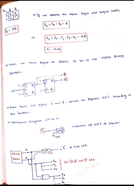
By Using Binary counter, some Gates and relays, we can design this lighting sequence of LEDs.

 Note:- If you are confusing to
understand, Feel free to ask me. I will clarify you clearly.
Note:- If you are confusing to
understand, Feel free to ask me. I will clarify you clearly.
Add Answer to:
Design a digital systems that forces LEDs to blink one after
another in the following order:...
Hello, I'm taking Digital logic design and have been stuck on this can I get the solution for this? how I am going to create the circuit? what I'm looking for is to do it with Shift Registers....
 Hello, I'm taking Digital logic design and have been stuck on
this can I get the solution for this?
how I am going to create the circuit?
what I'm looking for is to do it with Shift Registers. is it
possible?
Design a digital systems that forces 8 LEDs to blink one after
another in the following order: 1 by 1, then 2 by 2, then 3 by 3,
until they finally all of them light up and then go...
Hello, I'm taking Digital logic design and have been stuck on
this can I get the solution for this?
how I am going to create the circuit?
what I'm looking for is to do it with Shift Registers. is it
possible?
Design a digital systems that forces 8 LEDs to blink one after
another in the following order: 1 by 1, then 2 by 2, then 3 by 3,
until they finally all of them light up and then go...
Lab 1-Lab Portion Part I Copy the Blink program from Figure 1-13 (page 17) in the textbook and run it on your Arduino. After verifying that the Blink program works, modify the program to make the...
 Lab 1-Lab Portion Part I Copy the Blink program from Figure 1-13 (page 17) in the textbook and run it on your Arduino. After verifying that the Blink program works, modify the program to make the on-board LED attached to pin #13 blink out "SOS" in Morse code. Use a 2 750 millisecond for long pulses. 50 millisecond for short pulses and a Part 2, Write a program that uses two pushbuttons to increase or decrease the brightness of the...
QUESTION 6 Зро Design a second-order IIR digital low-pass filter using Butterworth approximation....
 QUESTION 6 Зро Design a second-order IIR digital low-pass filter using Butterworth approximation. Use the bilinear transformation to convert the analogue fiter to a digital one (choose the sampling period T- 2 s and the cut-off frequency as 1 rad/'s). Express the digital transfer function of the filter H(z) as: In the box below, provide the numerical answer for b1. [Note: Don't normalise the transfer func on, i.e. b0 # 1). r98111acontentid1837836_1&step QUESTION 7 Windowing based FIR filter design techniques...
Track tickets to digital point of sale system, design and build that point of sale program...
 Track tickets to digital point of sale system, design and
build that point of sale program for them. Please help due very
soon!
1. Allow the waitstaff to input the table number, and the number of diners at this table o Each table can seat up to 4 diners 2. For each diner at the table, the system must: 1. Display a menu of at least 7 common breakfast items 2. Allow the waitstaff to enter the items the diner...
Track tickets to digital point of sale system, design and
build that point of sale program for them. Please help due very
soon!
1. Allow the waitstaff to input the table number, and the number of diners at this table o Each table can seat up to 4 diners 2. For each diner at the table, the system must: 1. Display a menu of at least 7 common breakfast items 2. Allow the waitstaff to enter the items the diner...
Write the following program to be executed on the FPGA board. 1. Write a VHDL model...
 Write the following program to be executed on the FPGA board. 1. Write a VHDL model for a code detector as shown in the Figure. The keypad is used to unlock a door. Pressing the start button followed by the sequence red-green-red-blue unlocks the door, no other sequence can open the door. Assume the clock is slowed down and each pressing of a button is detected once. For example when red is pressed it is only detected as pressed for...
Digital Logic Design Need help with homework. Also need to create Logisim circuit with results. T...
 Digital Logic Design
Need help with homework.
Also need to create Logisim circuit with results.
Thank you!
Your IDs gn project, spring semester Your name 19 Digital Logic Design. Mid-semester desi This is a synchronous counter design. Tables and Karnaugh maps are provided. Do this alone, do not consult with friends except for general structions guidance-I want to see your design. Design, Synchronous counter. (#2 of 3) (repeat). That is QdQcQbQa-0001 (one), 0010 (t Note: Qa is the I.s.b. Design...
Digital Logic Design
Need help with homework.
Also need to create Logisim circuit with results.
Thank you!
Your IDs gn project, spring semester Your name 19 Digital Logic Design. Mid-semester desi This is a synchronous counter design. Tables and Karnaugh maps are provided. Do this alone, do not consult with friends except for general structions guidance-I want to see your design. Design, Synchronous counter. (#2 of 3) (repeat). That is QdQcQbQa-0001 (one), 0010 (t Note: Qa is the I.s.b. Design...
Design a Mealy FSM that will model an elevator that can be at any of 4...
Design a Mealy FSM that will model an elevator that can be at any of 4 floors of EPIC (Ground, First, Second, and Third). There are 2 input buttons that are active High – U to move UP and D to move DOWN. The input buttons are mutually exclusive, that is, only one of them can be active at any point in time (U = 0 and D = 1 makes it go DOWN, and U = 1 and D...
I ELE230L Digital Systems Design Laboratory Lab9 - Serial Adder Vaughn College of Aeronautics and...
 I need help putting this serial adder block diagram
into multisim software
I ELE230L Digital Systems Design Laboratory Lab9 - Serial Adder Vaughn College of Aeronautics and Technology Number of Lab Session (Week): 2 1 Discussion The purpose of this lab is to design, simulate, and implement a 4-bit serial adder SADD. A block diagram is shown below. The SADD has two int bit FA with a carry-hold flip-flop. Its input is a 4-bit data input (D-Do), a rising edge...
I need help putting this serial adder block diagram
into multisim software
I ELE230L Digital Systems Design Laboratory Lab9 - Serial Adder Vaughn College of Aeronautics and Technology Number of Lab Session (Week): 2 1 Discussion The purpose of this lab is to design, simulate, and implement a 4-bit serial adder SADD. A block diagram is shown below. The SADD has two int bit FA with a carry-hold flip-flop. Its input is a 4-bit data input (D-Do), a rising edge...
2. Design a digital lowpass filter to meet the following specifications: passband edge = 0.45π stopband...
2. Design a digital lowpass filter to meet the following specifications: passband edge = 0.45π stopband edge = 0.5π Rp = 0.5 dB, As = 60 dB a. Design a Buttterworth filter, you may use the butterord and butter commands to implement. b. Design Chebyshev Type 1 filter ( use the equivalent commands to above ) c. Design an Elliptic fitler ( use the equivalent commands to part a ). d. List the order of each filter and find the...
Four different designs for a digital computer circuit are being studied in order to compare the...
Four different designs for a digital computer circuit are being studied in order to compare the amount of noise present. Determine whether the amount of noise present is the same for all four design based on the following data. Circuits Noise Observed 1 19 20 19 21 24 2 40 41 43 46 40 3 28 26 25 31 20 4 79 68 77 78 67 ANOVA 1. What type of experimental design is employed in this problem? 2. Identify...
 Hello, I'm taking Digital logic design and have been stuck on
this can I get the solution for this?
how I am going to create the circuit?
what I'm looking for is to do it with Shift Registers. is it
possible?
Design a digital systems that forces 8 LEDs to blink one after
another in the following order: 1 by 1, then 2 by 2, then 3 by 3,
until they finally all of them light up and then go...
Hello, I'm taking Digital logic design and have been stuck on
this can I get the solution for this?
how I am going to create the circuit?
what I'm looking for is to do it with Shift Registers. is it
possible?
Design a digital systems that forces 8 LEDs to blink one after
another in the following order: 1 by 1, then 2 by 2, then 3 by 3,
until they finally all of them light up and then go...
 Lab 1-Lab Portion Part I Copy the Blink program from Figure 1-13 (page 17) in the textbook and run it on your Arduino. After verifying that the Blink program works, modify the program to make the on-board LED attached to pin #13 blink out "SOS" in Morse code. Use a 2 750 millisecond for long pulses. 50 millisecond for short pulses and a Part 2, Write a program that uses two pushbuttons to increase or decrease the brightness of the...
 QUESTION 6 Зро Design a second-order IIR digital low-pass filter using Butterworth approximation. Use the bilinear transformation to convert the analogue fiter to a digital one (choose the sampling period T- 2 s and the cut-off frequency as 1 rad/'s). Express the digital transfer function of the filter H(z) as: In the box below, provide the numerical answer for b1. [Note: Don't normalise the transfer func on, i.e. b0 # 1). r98111acontentid1837836_1&step QUESTION 7 Windowing based FIR filter design techniques...
 Track tickets to digital point of sale system, design and
build that point of sale program for them. Please help due very
soon!
1. Allow the waitstaff to input the table number, and the number of diners at this table o Each table can seat up to 4 diners 2. For each diner at the table, the system must: 1. Display a menu of at least 7 common breakfast items 2. Allow the waitstaff to enter the items the diner...
Track tickets to digital point of sale system, design and
build that point of sale program for them. Please help due very
soon!
1. Allow the waitstaff to input the table number, and the number of diners at this table o Each table can seat up to 4 diners 2. For each diner at the table, the system must: 1. Display a menu of at least 7 common breakfast items 2. Allow the waitstaff to enter the items the diner...
 Write the following program to be executed on the FPGA board. 1. Write a VHDL model for a code detector as shown in the Figure. The keypad is used to unlock a door. Pressing the start button followed by the sequence red-green-red-blue unlocks the door, no other sequence can open the door. Assume the clock is slowed down and each pressing of a button is detected once. For example when red is pressed it is only detected as pressed for...
 Digital Logic Design
Need help with homework.
Also need to create Logisim circuit with results.
Thank you!
Your IDs gn project, spring semester Your name 19 Digital Logic Design. Mid-semester desi This is a synchronous counter design. Tables and Karnaugh maps are provided. Do this alone, do not consult with friends except for general structions guidance-I want to see your design. Design, Synchronous counter. (#2 of 3) (repeat). That is QdQcQbQa-0001 (one), 0010 (t Note: Qa is the I.s.b. Design...
Digital Logic Design
Need help with homework.
Also need to create Logisim circuit with results.
Thank you!
Your IDs gn project, spring semester Your name 19 Digital Logic Design. Mid-semester desi This is a synchronous counter design. Tables and Karnaugh maps are provided. Do this alone, do not consult with friends except for general structions guidance-I want to see your design. Design, Synchronous counter. (#2 of 3) (repeat). That is QdQcQbQa-0001 (one), 0010 (t Note: Qa is the I.s.b. Design...
 I need help putting this serial adder block diagram
into multisim software
I ELE230L Digital Systems Design Laboratory Lab9 - Serial Adder Vaughn College of Aeronautics and Technology Number of Lab Session (Week): 2 1 Discussion The purpose of this lab is to design, simulate, and implement a 4-bit serial adder SADD. A block diagram is shown below. The SADD has two int bit FA with a carry-hold flip-flop. Its input is a 4-bit data input (D-Do), a rising edge...
I need help putting this serial adder block diagram
into multisim software
I ELE230L Digital Systems Design Laboratory Lab9 - Serial Adder Vaughn College of Aeronautics and Technology Number of Lab Session (Week): 2 1 Discussion The purpose of this lab is to design, simulate, and implement a 4-bit serial adder SADD. A block diagram is shown below. The SADD has two int bit FA with a carry-hold flip-flop. Its input is a 4-bit data input (D-Do), a rising edge...
Most questions answered within 3 hours.
-
A regression equation that describes the relationship between
the amount of the bill ($) at a...
asked 36 minutes ago -
exercise on VSEPR and molecular structrue.
octahedral
SeCl62-
TeCl62-
ClF62-
distorted
SeF62–
IF6–
asked 1 hour ago -
284 mL of a 0.52 M potassium hydroxide solution is added to 467
mL of a...
asked 1 hour ago -
Little’s Law: Val d’Costa is a world famous ski village in the
French Alps. Because of...
asked 1 hour ago -
Find the absolute error D for the calculation if A + B/C=D A=
9.4 +/- 0.4...
asked 2 hours ago -
New Air Heating and Cooling, manufactures furnaces and central
air units. The company pride itself on...
asked 2 hours ago -
A coach uses a new technique to train gymnasts. Seven
gymnasts were randomly selected and their...
asked 4 hours ago -
While rotating the tires on your car you notice a rock [mass =
0.1 Kg] stuck...
asked 6 hours ago -
Using MARS simulator, write MIPS programs according to
the following scenarios: Receive a positive integer number...
asked 8 hours ago -
An object in front of a concave mirror has a real image that is
11.5 cm...
asked 8 hours ago -
Consider the reaction, C3 H8 + O2 --> CO2 + H2O. How many
moles of O2...
asked 10 hours ago -
You and your opponent both roll a fair die. If you both roll the
same number,...
asked 10 hours ago