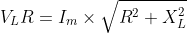
Using the data you collected in Table 1, from the first frequency that you collected data,...
- Using the data you collected in Table 1, from the first
frequency that you collected data, and using R, r, XL
and XC, draw to scale a phasor diagram to determine Z
and φ. Below is Table 1
Make a second drawing for the second frequency for which you collected data. Assume the phase angle for the capacitor is 90o. Below is second frequency and data from table 1.f (Hz)
R (Ω)
Vsource (V)
VC (V)
VLr (V)
VLR (V)
VR (V)
0.5
10
10
1
10
10
3.5
Answer these questions for each drawing:1.5
10
10
0.1
10
10
1.0
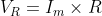
- Does Vsource = IZ?
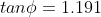
- What is the phase angle in the drawing?
Homework Answers


as the circuit is in series therefore current in all components is same


(B) for second table
as the circuit is in series therefore current in all components is same

(B) for second table


as the circuit is in series therefore current in all components is same


as the circuit is in series therefore current in all components is same


(B) for second table
as the circuit is in series therefore current in all components is same

(B) for second table


as the circuit is in series therefore current in all components is same


Add Answer to:
Using the data you collected in Table 1, from the first
frequency that you collected data,...
Consider an RLC series circuit with R = 600 Ω, L = 3 H, C =...
Consider an RLC series circuit with R = 600 Ω, L = 3 H, C = 4μF, generator voltage V = 20 v, frequency= 60 hz. Find a) the inductive impedance XL, b) capacitive impedance Xc , c) Total impedance Z, d) Line current I , e) Voltage drops VR , VL, ,Vc f) combination voltage VRL , and VLc , g) phase angle φ , h) resonant frequency f0 , i) Power dissipated by circuit.
Procedure Table 1 Voltage Generated, v Voltage across R, VR (V) Current IR, (A) 1 V...
 Procedure Table 1 Voltage Generated, v Voltage across R, VR (V) Current IR, (A) 1 V 0.194 0.021 2 V 0.393 0.041 3 V 0.593 0.061 4 V 0.794 0.081 5 V 0.995 0.101 Average 0.593 0.061 Procedure 2 Setup Procedure Procedure 2 Setup Procedure Table 2 Voltage Generated, v Voltage across R, VRC (V) Voltage across C, Vc (V) 1V 0.161 0.526 2 V 0.322 1.052 3 V 0.489 1.586 4 V 0.651 2.109 5 V 0.816 2.647 Average...
Consider the RLC circuit below, with R= 20 12, L = 10 mH, and C =...
 Consider the RLC circuit below, with R= 20 12, L = 10 mH, and C = 5 mF. The voltage source has a voltage amplitude of 26.0 V and an angular frequency of w = 500 rad/s. a) What is the total impedance of the circuit? b) Find the amplitude of the current, and the phase angle, d. c) Draw a phasor diagram of the impedances. Be sure to clearly label Z, R, XL, Xc, and 0. R C E
1 ) A series circuit consisted of R= 10 KΩ, L= 42 mH , C= 2.1...
 1 ) A series circuit consisted of R= 10 KΩ, L= 42 mH , C= 2.1 µF
is connected to an alternative voltage with maximum voltage of
Vm = 24 V and frequency of 300.0 Hz.
Find the following:
Show the formula for each question. Show your
Calculations – put result in a box with its unit. Please write your
answer under each question
a)Find the value of angular frequency ω .
b) Inductive Reactance ( XL)
c)Capacitive Reactance (...
1 ) A series circuit consisted of R= 10 KΩ, L= 42 mH , C= 2.1 µF
is connected to an alternative voltage with maximum voltage of
Vm = 24 V and frequency of 300.0 Hz.
Find the following:
Show the formula for each question. Show your
Calculations – put result in a box with its unit. Please write your
answer under each question
a)Find the value of angular frequency ω .
b) Inductive Reactance ( XL)
c)Capacitive Reactance (...
.Single-Frequency Analysis VR 1 + 0000 The circuit has L 100 mH, R 1 kn, C...
 .Single-Frequency Analysis VR 1 + 0000 The circuit has L 100 mH, R 1 kn, C 0.05 F, and the sinusoidal source is described by: L vg V. 10 cos(27nft+ 90°) V where f 3 kHz In this step for single-frequency analysis, find the magnitudes and phases of V VR, Vc, and the current in the series circuit by L performing an analytical solution using phasor analysis. Then, you are to use PSpice to find these same magnitudes and phases...
I am currently trying to figure out the experiment below. Please complete Table 1 with an...
 I am currently trying to figure out the experiment below. Please
complete Table 1 with an explanation, I appreciate it thank
you! Promise to give thumbs up!
Introduction The phase differences between the output voltage, the voltage across the inductor, the voltage across the capacitor, and the voltage across the resistor will be examined at resonant frequency. The voltage and phase relationship will also be examined for frequencies above and below resonance. Theory An inductor, a capacitor, and a resistor are...
I am currently trying to figure out the experiment below. Please
complete Table 1 with an explanation, I appreciate it thank
you! Promise to give thumbs up!
Introduction The phase differences between the output voltage, the voltage across the inductor, the voltage across the capacitor, and the voltage across the resistor will be examined at resonant frequency. The voltage and phase relationship will also be examined for frequencies above and below resonance. Theory An inductor, a capacitor, and a resistor are...
INSTRUCTIONS: Read the questions carefully and answer the following items accordingly. Show your solution properly. Q7...
 INSTRUCTIONS: Read the questions carefully and answer the following items accordingly. Show your solution properly. Q7 A technician made an experiment of an AC circuit in an electrical lab. The source voltage is AC with a frequency of 60Hz. He collected the data in the form of a phasor diagram as shown Figure 3. This phasor diagram is an impedance phasor. The values in the diagram are reactances, a resistance and current. The current in this case is the reference...
I need help completing the answer the formula's is given for each part. Thank you. The...
 I need help completing the answer the formula's is given for
each part. Thank you.
The provided series RLC circuit is in a sinusoidal steady state at a frequency of 60 Hz. V = 100 V, R = 20 L = 15 mH.C = 150 F (t) Cl2 a) Calculate the magnitude (12) and phase angle () of the load. XL2WL عليا function of z = f(R, XL, XC) M = f(R, XL,XC) b) Calculate the source currentl. JE VLO...
I need help completing the answer the formula's is given for
each part. Thank you.
The provided series RLC circuit is in a sinusoidal steady state at a frequency of 60 Hz. V = 100 V, R = 20 L = 15 mH.C = 150 F (t) Cl2 a) Calculate the magnitude (12) and phase angle () of the load. XL2WL عليا function of z = f(R, XL, XC) M = f(R, XL,XC) b) Calculate the source currentl. JE VLO...
EXERCISE 2: USING PHASORS FOR A DRIVEN RC CIRCUIT 10. On the middle set of axes,...
 EXERCISE 2: USING PHASORS FOR A DRIVEN RC CIRCUIT 10. On the middle set of axes, draw phasors for k and ε using the provided ve phasor as a basis for a circuit in which R- 2Xc. Start by deciding what the peak voltage across the capacitor must be compared to the peak voltage across the resistor and then draw the appropriate Vc phasor We will consider a circuit consisting of a time varying emf in series with a capacitor...
B oth 100 Day PH262 Page 1 of 5 Lab #13 AC Circuits, Part 1 RC...
 B oth 100 Day PH262 Page 1 of 5 Lab #13 AC Circuits, Part 1 RC & RL, Phase Measurements THEORY The rotating phase representation for series AC circuits should be familiar from textbook and lecture notes A brief outline of the essential points is provided here. If a series RLC circuit is connected across a source of om which is a sinusoidal function of time, then und all its derivatives will also be inside. Sonce all demits in a...
 Procedure Table 1 Voltage Generated, v Voltage across R, VR (V) Current IR, (A) 1 V 0.194 0.021 2 V 0.393 0.041 3 V 0.593 0.061 4 V 0.794 0.081 5 V 0.995 0.101 Average 0.593 0.061 Procedure 2 Setup Procedure Procedure 2 Setup Procedure Table 2 Voltage Generated, v Voltage across R, VRC (V) Voltage across C, Vc (V) 1V 0.161 0.526 2 V 0.322 1.052 3 V 0.489 1.586 4 V 0.651 2.109 5 V 0.816 2.647 Average...
 Consider the RLC circuit below, with R= 20 12, L = 10 mH, and C = 5 mF. The voltage source has a voltage amplitude of 26.0 V and an angular frequency of w = 500 rad/s. a) What is the total impedance of the circuit? b) Find the amplitude of the current, and the phase angle, d. c) Draw a phasor diagram of the impedances. Be sure to clearly label Z, R, XL, Xc, and 0. R C E
 1 ) A series circuit consisted of R= 10 KΩ, L= 42 mH , C= 2.1 µF
is connected to an alternative voltage with maximum voltage of
Vm = 24 V and frequency of 300.0 Hz.
Find the following:
Show the formula for each question. Show your
Calculations – put result in a box with its unit. Please write your
answer under each question
a)Find the value of angular frequency ω .
b) Inductive Reactance ( XL)
c)Capacitive Reactance (...
1 ) A series circuit consisted of R= 10 KΩ, L= 42 mH , C= 2.1 µF
is connected to an alternative voltage with maximum voltage of
Vm = 24 V and frequency of 300.0 Hz.
Find the following:
Show the formula for each question. Show your
Calculations – put result in a box with its unit. Please write your
answer under each question
a)Find the value of angular frequency ω .
b) Inductive Reactance ( XL)
c)Capacitive Reactance (...
 .Single-Frequency Analysis VR 1 + 0000 The circuit has L 100 mH, R 1 kn, C 0.05 F, and the sinusoidal source is described by: L vg V. 10 cos(27nft+ 90°) V where f 3 kHz In this step for single-frequency analysis, find the magnitudes and phases of V VR, Vc, and the current in the series circuit by L performing an analytical solution using phasor analysis. Then, you are to use PSpice to find these same magnitudes and phases...
 I am currently trying to figure out the experiment below. Please
complete Table 1 with an explanation, I appreciate it thank
you! Promise to give thumbs up!
Introduction The phase differences between the output voltage, the voltage across the inductor, the voltage across the capacitor, and the voltage across the resistor will be examined at resonant frequency. The voltage and phase relationship will also be examined for frequencies above and below resonance. Theory An inductor, a capacitor, and a resistor are...
I am currently trying to figure out the experiment below. Please
complete Table 1 with an explanation, I appreciate it thank
you! Promise to give thumbs up!
Introduction The phase differences between the output voltage, the voltage across the inductor, the voltage across the capacitor, and the voltage across the resistor will be examined at resonant frequency. The voltage and phase relationship will also be examined for frequencies above and below resonance. Theory An inductor, a capacitor, and a resistor are...
 INSTRUCTIONS: Read the questions carefully and answer the following items accordingly. Show your solution properly. Q7 A technician made an experiment of an AC circuit in an electrical lab. The source voltage is AC with a frequency of 60Hz. He collected the data in the form of a phasor diagram as shown Figure 3. This phasor diagram is an impedance phasor. The values in the diagram are reactances, a resistance and current. The current in this case is the reference...
 I need help completing the answer the formula's is given for
each part. Thank you.
The provided series RLC circuit is in a sinusoidal steady state at a frequency of 60 Hz. V = 100 V, R = 20 L = 15 mH.C = 150 F (t) Cl2 a) Calculate the magnitude (12) and phase angle () of the load. XL2WL عليا function of z = f(R, XL, XC) M = f(R, XL,XC) b) Calculate the source currentl. JE VLO...
I need help completing the answer the formula's is given for
each part. Thank you.
The provided series RLC circuit is in a sinusoidal steady state at a frequency of 60 Hz. V = 100 V, R = 20 L = 15 mH.C = 150 F (t) Cl2 a) Calculate the magnitude (12) and phase angle () of the load. XL2WL عليا function of z = f(R, XL, XC) M = f(R, XL,XC) b) Calculate the source currentl. JE VLO...
 EXERCISE 2: USING PHASORS FOR A DRIVEN RC CIRCUIT 10. On the middle set of axes, draw phasors for k and ε using the provided ve phasor as a basis for a circuit in which R- 2Xc. Start by deciding what the peak voltage across the capacitor must be compared to the peak voltage across the resistor and then draw the appropriate Vc phasor We will consider a circuit consisting of a time varying emf in series with a capacitor...
 B oth 100 Day PH262 Page 1 of 5 Lab #13 AC Circuits, Part 1 RC & RL, Phase Measurements THEORY The rotating phase representation for series AC circuits should be familiar from textbook and lecture notes A brief outline of the essential points is provided here. If a series RLC circuit is connected across a source of om which is a sinusoidal function of time, then und all its derivatives will also be inside. Sonce all demits in a...
Most questions answered within 3 hours.
-
Little’s Law: Val d’Costa is a world famous ski village in the
French Alps. Because of...
asked 2 minutes ago -
Find the absolute error D for the calculation if A + B/C=D A=
9.4 +/- 0.4...
asked 15 minutes ago -
New Air Heating and Cooling, manufactures furnaces and central
air units. The company pride itself on...
asked 29 minutes ago -
A coach uses a new technique to train gymnasts. Seven
gymnasts were randomly selected and their...
asked 2 hours ago -
While rotating the tires on your car you notice a rock [mass =
0.1 Kg] stuck...
asked 4 hours ago -
Using MARS simulator, write MIPS programs according to
the following scenarios: Receive a positive integer number...
asked 6 hours ago -
An object in front of a concave mirror has a real image that is
11.5 cm...
asked 6 hours ago -
Consider the reaction, C3 H8 + O2 --> CO2 + H2O. How many
moles of O2...
asked 8 hours ago -
You and your opponent both roll a fair die. If you both roll the
same number,...
asked 8 hours ago -
In a study of the accuracy of fast food drive-through orders,
Restaurant A had 257 accurate...
asked 8 hours ago -
Identify and describe in detail the four categories of
institutions that could be included in a...
asked 8 hours ago -
In python
class Customer:
def __init__(self, customer_id, last_name, first_name, phone_number, address):
self._customer_id = int(customer_id)
self._last_name =...
asked 8 hours ago