1. The difference equation for a single stage RC circuit, when the input is 1v., is &...
1. The difference equation for a single stage RC circuit, when the
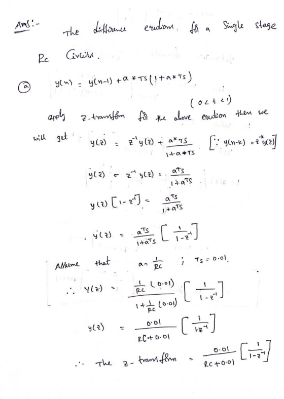
input is 1v., is
shown below (see Lab 4):
y(n) = (y(n-1) + a * Ts) / (1 + a * Ts) (0 < t < 1)
where a = 1 / (RC)
Ignore the difference equation for the case t > 1, when the input is 0v.
(a) Find the Z-transform of y(n) analytically,
assuming a time constant of a = 5 and sampling interval of Ts =
0.1. Then apply MATLAB’s iztrans function to generate y as a
vector, and display the values of y(n) using
y =
abs(double(subs(y, n))); y = [0, y]
(b) Verify the result with MATLAB using the for loop below. Note that k = a*Ts.
y(1) = 0;
for n = 1:11
y(n+1) =
(y(n) + k) / (1 + k);
end
y
(c) Repeat parts (a) and (b), changing the time
constant from 5 to 1. Your results should be consistent with those
from Lab 4. The sampling time has been changed from 0.01 to 0.1,
resulting in the value at t = 1 corresponding to n = 10, instead
of
n = 100.
2. (a) Verify the output sequence for the two stage RC
circuit (see Lab 6) using MATLAB’s iztrans function.
(b) Find the output sequence y(n) analytically using the Z-transform, residues and the inverse Z-transform.
Homework Answers


Add Answer to:
1. The difference equation for a single stage RC circuit, when the input is 1v., is &...
3. (a) Verify the output sequence for the two stage RC circuit (see Lab 6) using MATLAB's iztrans...
 3. (a) Verify the output sequence for the two stage RC circuit (see Lab 6) using MATLAB's iztrans function. (b) Required only for students in EENG 6633 Find the output sequence y(n) analytically using the Z-transform, residues and the inverse Z-transform. R1R2 七 七
3. (a) Verify the output sequence for the two stage RC circuit (see Lab 6) using MATLAB's iztrans function. (b) Required only for students in EENG 6633 Find the output sequence y(n) analytically using the Z-transform,...
3. (a) Verify the output sequence for the two stage RC circuit (see Lab 6) using MATLAB's iztrans function. (b) Required only for students in EENG 6633 Find the output sequence y(n) analytically using the Z-transform, residues and the inverse Z-transform. R1R2 七 七
3. (a) Verify the output sequence for the two stage RC circuit (see Lab 6) using MATLAB's iztrans function. (b) Required only for students in EENG 6633 Find the output sequence y(n) analytically using the Z-transform,...
Consider an LTI system with input sequence x[n] and output sequence y[n] that satisfy the difference equation
Consider an LTI system with input sequence x[n] and output sequence y[n] that satisfy the difference equation 3y[n] – 7y[n – 1] + 2y[n – 2] = 3x[n] – 3x[n – 1] (2.1) The fact that sequences x[ ] and y[ ] are in input-output relation and satisfy (2.1) does not yet determine which LTI system. a) We assume each possible input sequence to this system has its Z-transform and that the impulse response of this system also has its Z-transform. Express the...
1. Calculate the RC time constant of the circuit in Fig. 1 using equation (1) 2....
 1. Calculate the RC time constant of the circuit in Fig.
1 using equation (1)
2. Derive expressions of Vout(t) for circuits in
Figs. 1 and 2
3. Sketch your derived results for Vout(t), clearly
labeling your initial voltages and time constants
10 k22 M + + Vin 0.1 uf Vout Fig. 1. RC circuit 0.1 uf + + Vin 10 k2 Vout Fig. 2. RC circuit.
1. Calculate the RC time constant of the circuit in Fig.
1 using equation (1)
2. Derive expressions of Vout(t) for circuits in
Figs. 1 and 2
3. Sketch your derived results for Vout(t), clearly
labeling your initial voltages and time constants
10 k22 M + + Vin 0.1 uf Vout Fig. 1. RC circuit 0.1 uf + + Vin 10 k2 Vout Fig. 2. RC circuit.
Consider a high-pass RC circuit shown below. Let the capacitor be initially uncharged, and the input...
 Consider a high-pass RC circuit shown below. Let the capacitor be initially uncharged, and the input v;(t) be applied at t= 0. v;(t) SR v.(t) (a) Obtain the differential equation governing the input and output voltages for t > 0. (b) Using trapezoidal rule convert the same into a difference equation. (c) Obtain the response v.(t) by solving the differential equation. a sampling For numerical values of R = 80092 and C = 0.754F and for vi(t) = A coswt,...
We may design a DC power supply by cascading a fullwave rectifier and an RC circuit as depicted b...
 We may design a DC power supply by cascading a fullwave rectifier and an RC circuit as depicted below. The full-wave rectifier output is given by z(t) x(t) Let H(ja) be the frequency response of the RC circuit. Suppose the input x(t) cos(120rt), a) Write the Trigonometric Fourier series representation of z(t) b) Write the Trigonometric Fourier series representation of y(t) c) Find the range for the time constant RC such that the first harmonic of the ripple in y(t)...
Problem 24: (18 points) 1. (6 points) Figure 2 shows an RC circuit with input f(t)...
 Problem 24: (18 points) 1. (6 points) Figure 2 shows an RC circuit with input f(t) and output y(t) Function Generator R, v, (r) y1) Figure 2: RC circuit. (a) (1 point) Sketch the circuit in the phasor domain by replacing the capacitor with its impedance represen- (b) (3 points) Using circuit analysis techniques, show that the frequency response function is Specify the DC gain, K, and the time constant, T, in terms of the parameters R, R, and C...
5) A single-input (x) single-output(z) synchronous sequential circuit is required to operate as follows: i) The...
 5) A single-input (x) single-output(z) synchronous sequential circuit is required to operate as follows: i) The circuit is put to a specific initial state (call this state A) ii) Starting from state A, the circuit will give a 1 output when the input sequence up to and including the present time contains an odd number of 0's and an odd number of l's: the circuit will give a 0 output at all other times An example input and corresponding output...
-1 3. Apply the periodic signal o I to a system (the RC circuit discussed in...
 -1 3. Apply the periodic signal o I to a system (the RC circuit discussed in class) for which I+ oRC Use MATLAB to plot the output signal ) (which corresponds to the capacitor voltage) for three cases, namely RC-see, RC-10see a RC-0.1se Compare the output to the input signal and discuss the amount of distortion that is observed and why in some cases there is more distortion than in other cases. Hint: you will need to where τ is...
Question 3. Consider the DT system described by the difference equation y[n+1]+ 0.3 y[n] 0.4x[n] Using...
 Question 3. Consider the DT system described by the difference equation y[n+1]+ 0.3 y[n] 0.4x[n] Using the Z-transform, determine the system's zero-input response for the initial value of y[0] 1/3. The solution directly in the time domain is not accepted
(c) A digital filter has transfer function 1 Н(2) z 1/2 Evaluate the response function of...
 (c) A digital filter has transfer function 1 Н(2) z 1/2 Evaluate the response function of the filter, Y(z)= X(z)H(z), for the sequence (i 2* x(n)a. (Use the geometric series 1-c k 0 (ii By using partial fractions, determine the response of the filter, y(n), to the input x(п) %— а". (iii What is the response to the input data x(n) (1)"? [Note: the Z- transform of a sequence x(n) is defined as X(z) x(n)z. The n-0 inverse Z- transform...
 3. (a) Verify the output sequence for the two stage RC circuit (see Lab 6) using MATLAB's iztrans function. (b) Required only for students in EENG 6633 Find the output sequence y(n) analytically using the Z-transform, residues and the inverse Z-transform. R1R2 七 七
3. (a) Verify the output sequence for the two stage RC circuit (see Lab 6) using MATLAB's iztrans function. (b) Required only for students in EENG 6633 Find the output sequence y(n) analytically using the Z-transform,...
3. (a) Verify the output sequence for the two stage RC circuit (see Lab 6) using MATLAB's iztrans function. (b) Required only for students in EENG 6633 Find the output sequence y(n) analytically using the Z-transform, residues and the inverse Z-transform. R1R2 七 七
3. (a) Verify the output sequence for the two stage RC circuit (see Lab 6) using MATLAB's iztrans function. (b) Required only for students in EENG 6633 Find the output sequence y(n) analytically using the Z-transform,...
 1. Calculate the RC time constant of the circuit in Fig.
1 using equation (1)
2. Derive expressions of Vout(t) for circuits in
Figs. 1 and 2
3. Sketch your derived results for Vout(t), clearly
labeling your initial voltages and time constants
10 k22 M + + Vin 0.1 uf Vout Fig. 1. RC circuit 0.1 uf + + Vin 10 k2 Vout Fig. 2. RC circuit.
1. Calculate the RC time constant of the circuit in Fig.
1 using equation (1)
2. Derive expressions of Vout(t) for circuits in
Figs. 1 and 2
3. Sketch your derived results for Vout(t), clearly
labeling your initial voltages and time constants
10 k22 M + + Vin 0.1 uf Vout Fig. 1. RC circuit 0.1 uf + + Vin 10 k2 Vout Fig. 2. RC circuit.
 Consider a high-pass RC circuit shown below. Let the capacitor be initially uncharged, and the input v;(t) be applied at t= 0. v;(t) SR v.(t) (a) Obtain the differential equation governing the input and output voltages for t > 0. (b) Using trapezoidal rule convert the same into a difference equation. (c) Obtain the response v.(t) by solving the differential equation. a sampling For numerical values of R = 80092 and C = 0.754F and for vi(t) = A coswt,...
 We may design a DC power supply by cascading a fullwave rectifier and an RC circuit as depicted below. The full-wave rectifier output is given by z(t) x(t) Let H(ja) be the frequency response of the RC circuit. Suppose the input x(t) cos(120rt), a) Write the Trigonometric Fourier series representation of z(t) b) Write the Trigonometric Fourier series representation of y(t) c) Find the range for the time constant RC such that the first harmonic of the ripple in y(t)...
 Problem 24: (18 points) 1. (6 points) Figure 2 shows an RC circuit with input f(t) and output y(t) Function Generator R, v, (r) y1) Figure 2: RC circuit. (a) (1 point) Sketch the circuit in the phasor domain by replacing the capacitor with its impedance represen- (b) (3 points) Using circuit analysis techniques, show that the frequency response function is Specify the DC gain, K, and the time constant, T, in terms of the parameters R, R, and C...
 5) A single-input (x) single-output(z) synchronous sequential circuit is required to operate as follows: i) The circuit is put to a specific initial state (call this state A) ii) Starting from state A, the circuit will give a 1 output when the input sequence up to and including the present time contains an odd number of 0's and an odd number of l's: the circuit will give a 0 output at all other times An example input and corresponding output...
 -1 3. Apply the periodic signal o I to a system (the RC circuit discussed in class) for which I+ oRC Use MATLAB to plot the output signal ) (which corresponds to the capacitor voltage) for three cases, namely RC-see, RC-10see a RC-0.1se Compare the output to the input signal and discuss the amount of distortion that is observed and why in some cases there is more distortion than in other cases. Hint: you will need to where τ is...
 Question 3. Consider the DT system described by the difference equation y[n+1]+ 0.3 y[n] 0.4x[n] Using the Z-transform, determine the system's zero-input response for the initial value of y[0] 1/3. The solution directly in the time domain is not accepted
 (c) A digital filter has transfer function 1 Н(2) z 1/2 Evaluate the response function of the filter, Y(z)= X(z)H(z), for the sequence (i 2* x(n)a. (Use the geometric series 1-c k 0 (ii By using partial fractions, determine the response of the filter, y(n), to the input x(п) %— а". (iii What is the response to the input data x(n) (1)"? [Note: the Z- transform of a sequence x(n) is defined as X(z) x(n)z. The n-0 inverse Z- transform...
Most questions answered within 3 hours.
-
Question :1 (40%, 8% per sub question)
A firm is evaluating two mutually exclusive projects that...
asked 6 minutes ago -
Acme Company insured its building on a replacement cost basis
for $700,000 under a property insurance...
asked 7 minutes ago -
Suppose 4.8 g of zinc is treated with 7.4 g of pure hydrogen
chloride. What is...
asked 15 minutes ago -
In an effort to cut down on garbage, Custodial Staff remove all
the garbage/recycling/compost cans from...
asked 16 minutes ago -
Access control is an important function in data security.
Specifically, tell me why access control is...
asked 23 minutes ago -
In the "Go" button add 15 random numbers in the array using a
random number generator....
asked 24 minutes ago -
5. Draw Molecular Orbital Diagrams for C2, C2 and C2. a. Determine the bond order for...
asked 3 years ago -
The emergency room at Hospital Systems, Inc (HIS) serves
patients who arrive according to
a Poisson...
asked 37 minutes ago -
The chickens at Colonel Thompson's Ranch have a mean weight of
1850 g, with a standard...
asked 50 minutes ago -
The time married men with children spend on child care averages
5.9 hours per week (Time,...
asked 55 minutes ago -
There are many minerals which contain sliver. One of them,
smithite, is placed in water and...
asked 53 minutes ago -
22.3 g of fructose, C6H12O6,
are dissolved completely in 75.5 mL of pure water at 20.0...
asked 1 hour ago