
Homework Answers


Add Answer to:
A plane truss element is shown in Figure 4, All elements have cross-sectional area of A = 8 in, a...
A plane truss element is shown in Figure 4. All elements have cross-sectional area of A = 8 in, a...
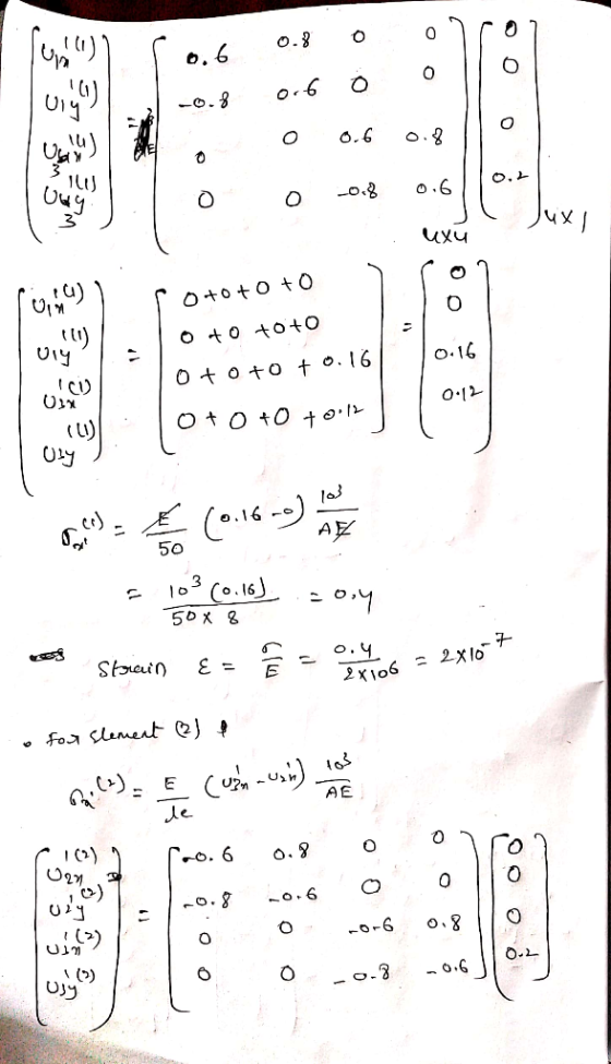
 A plane truss element is shown in Figure 4. All elements have cross-sectional area of A = 8 in, and elastic modulus of E 2 x 10 psi. Use long-hand solution. 6. 6.(a). Solve for the unknown displacements 6.(b). Solve for strains and stresses in all 3 elements. Show your work and follow the finite element method matrix formulation we have covered in lectures 4 3 20 ft 5 kip 10 kip 240 ft ft 30 ft- Figure 4
A...
A plane truss element is shown in Figure 4. All elements have cross-sectional area of A = 8 in, and elastic modulus of E 2 x 10 psi. Use long-hand solution. 6. 6.(a). Solve for the unknown displacements 6.(b). Solve for strains and stresses in all 3 elements. Show your work and follow the finite element method matrix formulation we have covered in lectures 4 3 20 ft 5 kip 10 kip 240 ft ft 30 ft- Figure 4
A...
Problem 1 The truss (all joints are pinned) structure in figure 1 is made of members with cross s...
 We were unable to transcribe this imageProblem 1 The truss (all joints are pinned) structure in figure 1 is made of members with cross sectional area A = 1 in, with a linear elastic, homogeneous, isotropic material with an elastic modulus. E-10E6 psi and a coefficient of thermal expansion, α-6E-6 °F-ι. The structure starts out at a uniform temperature of 65°F and is raised to a final temperature of 120°F while being subjected to a concentrated load Po- 5,000 lbs...
For the truss shown in the below figure, determine the stifness matrix for each truss element,...
 For the truss shown in the below figure, determine the stifness
matrix for each truss element, the stiffness matrix for entire
truss, the displacements at nodes 1 through 4, and the force in
elements 1 through 5. Also, determine the force in each element.
Let A = 3 in2, E = 30 x 106
psi for all elements.
8 kips 8 kips 10 ft. 3 4 2 トー-10ft.-*-10 ft.
For the truss shown in the below figure, determine the stifness
matrix for each truss element, the stiffness matrix for entire
truss, the displacements at nodes 1 through 4, and the force in
elements 1 through 5. Also, determine the force in each element.
Let A = 3 in2, E = 30 x 106
psi for all elements.
8 kips 8 kips 10 ft. 3 4 2 トー-10ft.-*-10 ft.
Problem 2: a. For the plane truss shown in Figure 2, determine the nodal displacements, the element forces and stresses, and the support reactions. All elements have E-70 GPa and A-25 cm 100 k...
 Problem 2: a. For the plane truss shown in Figure 2, determine the nodal displacements, the element forces and stresses, and the support reactions. All elements have E-70 GPa and A-25 cm 100 kN 50 kN 50 kN 4 4 6 Figure 2. Plane Truss
Problem 2: a. For the plane truss shown in Figure 2, determine the nodal displacements, the element forces and stresses, and the support reactions. All elements have E-70 GPa and A-25 cm 100 kN 50...
Problem 2: a. For the plane truss shown in Figure 2, determine the nodal displacements, the element forces and stresses, and the support reactions. All elements have E-70 GPa and A-25 cm 100 kN 50 kN 50 kN 4 4 6 Figure 2. Plane Truss
Problem 2: a. For the plane truss shown in Figure 2, determine the nodal displacements, the element forces and stresses, and the support reactions. All elements have E-70 GPa and A-25 cm 100 kN 50...
A plane structure consists of three truss elements connected to four nodes, as shown below. All t...
 A plane structure consists of three truss elements connected to four nodes, as shown below. All trusses have cross sectional area A -7.104 m2 and elastic modulus E = 210 GPa. The length of each truss element is L = 1 m. A point force, P -5 kN, is acting on node 4 L/2 3.1 Calculate the displacements at the nodes 3.2 Calculate the reaction forces 3.3 Calculate the stress in each bar
A plane structure consists of three truss...
A plane structure consists of three truss elements connected to four nodes, as shown below. All trusses have cross sectional area A -7.104 m2 and elastic modulus E = 210 GPa. The length of each truss element is L = 1 m. A point force, P -5 kN, is acting on node 4 L/2 3.1 Calculate the displacements at the nodes 3.2 Calculate the reaction forces 3.3 Calculate the stress in each bar
A plane structure consists of three truss...
Grid 4 Grid 3 Po 15 in Grid 1 Grid 2 10 in Figure 1: Problem...
 Grid 4 Grid 3 Po 15 in Grid 1 Grid 2 10 in Figure 1: Problem 1 Schematic Problem 1 The truss (all joints are pinned) structure in figure 1 is made of members with cross sectional area A- 1 in2, with a linear elastic, homogeneous, isotropic material with an elastic modulus, E, 10E6 psi and a coefficient of thermal expansion. α-6E-6 op-1. The structure starts out at a uniform temperature of 65°F and is raised to a final temperature...
Solve all problems using the finite element stiffness method. For the rigid frame shown in Figure...
 Solve all problems using the finite element stiffness method. For the rigid frame shown in Figure P5-4, determine (1) the nodal displacements and rotation at node 4, (2) the reactions, and (3) the forces in each element. Then check equilibrium at node 4. Finally, draw the shear force and bending moment diagrams for each element. LetE 30 x 103 ksi, A = 8 in,2 , and 1-800 in.4 for all elements. 20 kip 25 ft 25 ft- 40 ft 20...
Finite Element Method 5.17 Displacements of the three-member truss shown are confined to the plane of...
 Finite Element Method
5.17 Displacements of the three-member truss shown are confined to the plane of the figure, and points 1, 2 and 3 are fixed to the stationary rim. All members have the same A, E, and L a) Obtain the 2x2 stiffness matrix that operates on the horizontal and vertical degrees of freedom of the central node. b) Obtain the corresponding global force vector c) Solve for the displacements and for axial stress in member (2-4), when the...
Finite Element Method
5.17 Displacements of the three-member truss shown are confined to the plane of the figure, and points 1, 2 and 3 are fixed to the stationary rim. All members have the same A, E, and L a) Obtain the 2x2 stiffness matrix that operates on the horizontal and vertical degrees of freedom of the central node. b) Obtain the corresponding global force vector c) Solve for the displacements and for axial stress in member (2-4), when the...
Solve all problems using the finite element stiffness method. For the rigid frame shown in Figure P5-4, determine (1) the nodal displacements and rotation at node 4, (2) the reactions, and (3) the fo...
 Solve all problems using the finite element stiffness method. For the rigid frame shown in Figure P5-4, determine (1) the nodal displacements and rotation at node 4, (2) the reactions, and (3) the forces in each element. Then check equilibrium at node 4 Finally, draw the shear force and bending moment diagrams for each element. Let E 30x 103 ksi, A 8 in2, and I 800 in.4 for all elements. 20 kip 25 ft 25 ft 40 ft Figure P5-4...
Plane truss
 The lower-right joint of the three-member plane truss shown in Figure 2 is supportedby a skew roller. The truss members are of a solid circular cross section having diameterd D 25 mm and elastic modulus E D 50 GPa. The force P D 70 kN is applied to theunconstrained joint. Number the nodes and elements, and solve for unknown nodaldisplacements and reaction forces using:a) Master-slave method,b) Penalty element method,c) Lagrange multiplier method.
 A plane truss element is shown in Figure 4. All elements have cross-sectional area of A = 8 in, and elastic modulus of E 2 x 10 psi. Use long-hand solution. 6. 6.(a). Solve for the unknown displacements 6.(b). Solve for strains and stresses in all 3 elements. Show your work and follow the finite element method matrix formulation we have covered in lectures 4 3 20 ft 5 kip 10 kip 240 ft ft 30 ft- Figure 4
A...
A plane truss element is shown in Figure 4. All elements have cross-sectional area of A = 8 in, and elastic modulus of E 2 x 10 psi. Use long-hand solution. 6. 6.(a). Solve for the unknown displacements 6.(b). Solve for strains and stresses in all 3 elements. Show your work and follow the finite element method matrix formulation we have covered in lectures 4 3 20 ft 5 kip 10 kip 240 ft ft 30 ft- Figure 4
A...
 We were unable to transcribe this imageProblem 1 The truss (all joints are pinned) structure in figure 1 is made of members with cross sectional area A = 1 in, with a linear elastic, homogeneous, isotropic material with an elastic modulus. E-10E6 psi and a coefficient of thermal expansion, α-6E-6 °F-ι. The structure starts out at a uniform temperature of 65°F and is raised to a final temperature of 120°F while being subjected to a concentrated load Po- 5,000 lbs...
 For the truss shown in the below figure, determine the stifness
matrix for each truss element, the stiffness matrix for entire
truss, the displacements at nodes 1 through 4, and the force in
elements 1 through 5. Also, determine the force in each element.
Let A = 3 in2, E = 30 x 106
psi for all elements.
8 kips 8 kips 10 ft. 3 4 2 トー-10ft.-*-10 ft.
For the truss shown in the below figure, determine the stifness
matrix for each truss element, the stiffness matrix for entire
truss, the displacements at nodes 1 through 4, and the force in
elements 1 through 5. Also, determine the force in each element.
Let A = 3 in2, E = 30 x 106
psi for all elements.
8 kips 8 kips 10 ft. 3 4 2 トー-10ft.-*-10 ft.
 Problem 2: a. For the plane truss shown in Figure 2, determine the nodal displacements, the element forces and stresses, and the support reactions. All elements have E-70 GPa and A-25 cm 100 kN 50 kN 50 kN 4 4 6 Figure 2. Plane Truss
Problem 2: a. For the plane truss shown in Figure 2, determine the nodal displacements, the element forces and stresses, and the support reactions. All elements have E-70 GPa and A-25 cm 100 kN 50...
Problem 2: a. For the plane truss shown in Figure 2, determine the nodal displacements, the element forces and stresses, and the support reactions. All elements have E-70 GPa and A-25 cm 100 kN 50 kN 50 kN 4 4 6 Figure 2. Plane Truss
Problem 2: a. For the plane truss shown in Figure 2, determine the nodal displacements, the element forces and stresses, and the support reactions. All elements have E-70 GPa and A-25 cm 100 kN 50...
 A plane structure consists of three truss elements connected to four nodes, as shown below. All trusses have cross sectional area A -7.104 m2 and elastic modulus E = 210 GPa. The length of each truss element is L = 1 m. A point force, P -5 kN, is acting on node 4 L/2 3.1 Calculate the displacements at the nodes 3.2 Calculate the reaction forces 3.3 Calculate the stress in each bar
A plane structure consists of three truss...
A plane structure consists of three truss elements connected to four nodes, as shown below. All trusses have cross sectional area A -7.104 m2 and elastic modulus E = 210 GPa. The length of each truss element is L = 1 m. A point force, P -5 kN, is acting on node 4 L/2 3.1 Calculate the displacements at the nodes 3.2 Calculate the reaction forces 3.3 Calculate the stress in each bar
A plane structure consists of three truss...
 Grid 4 Grid 3 Po 15 in Grid 1 Grid 2 10 in Figure 1: Problem 1 Schematic Problem 1 The truss (all joints are pinned) structure in figure 1 is made of members with cross sectional area A- 1 in2, with a linear elastic, homogeneous, isotropic material with an elastic modulus, E, 10E6 psi and a coefficient of thermal expansion. α-6E-6 op-1. The structure starts out at a uniform temperature of 65°F and is raised to a final temperature...
 Solve all problems using the finite element stiffness method. For the rigid frame shown in Figure P5-4, determine (1) the nodal displacements and rotation at node 4, (2) the reactions, and (3) the forces in each element. Then check equilibrium at node 4. Finally, draw the shear force and bending moment diagrams for each element. LetE 30 x 103 ksi, A = 8 in,2 , and 1-800 in.4 for all elements. 20 kip 25 ft 25 ft- 40 ft 20...
 Finite Element Method
5.17 Displacements of the three-member truss shown are confined to the plane of the figure, and points 1, 2 and 3 are fixed to the stationary rim. All members have the same A, E, and L a) Obtain the 2x2 stiffness matrix that operates on the horizontal and vertical degrees of freedom of the central node. b) Obtain the corresponding global force vector c) Solve for the displacements and for axial stress in member (2-4), when the...
Finite Element Method
5.17 Displacements of the three-member truss shown are confined to the plane of the figure, and points 1, 2 and 3 are fixed to the stationary rim. All members have the same A, E, and L a) Obtain the 2x2 stiffness matrix that operates on the horizontal and vertical degrees of freedom of the central node. b) Obtain the corresponding global force vector c) Solve for the displacements and for axial stress in member (2-4), when the...
 Solve all problems using the finite element stiffness method. For the rigid frame shown in Figure P5-4, determine (1) the nodal displacements and rotation at node 4, (2) the reactions, and (3) the forces in each element. Then check equilibrium at node 4 Finally, draw the shear force and bending moment diagrams for each element. Let E 30x 103 ksi, A 8 in2, and I 800 in.4 for all elements. 20 kip 25 ft 25 ft 40 ft Figure P5-4...
Most questions answered within 3 hours.
-
If X is a binomial random variable with n = 8
and p = 0.2, the...
asked 57 seconds ago -
Seasonal or cyclical variation in a time-series model…
---exhibits irregular
variation that can be accounted for...
asked 2 minutes ago -
Please use Barney's VRIO framework of analysis to evaluate a
firm's competencies. Please choose a specific...
asked 14 minutes ago -
Where would you expect to have diabetes contributing to the most
DALYs in 2035, according to...
asked 16 minutes ago -
1.) Major league baseball salaries averaged $1.5 million with a
standard deviation of $1 million in...
asked 25 minutes ago -
A hedge fund is holding a three-year,
$10 million face value 6 percent annual coupon bond...
asked 36 minutes ago -
The focal length of a makeup (concave) mirror is 0.48 m. What
magnification does this mirror...
asked 40 minutes ago -
TRUE/FALSE
Long-lived assets that are tangible in nature, used in the
operations of the business, and...
asked 41 minutes ago -
A dragon biologist is setting up an experimental population of
1000 individuals. In dragons, pointy crests...
asked 52 minutes ago -
A uniform thin rod of length 0.851 m is hung from a horizontal
nail passing through...
asked 1 hour ago -
A 747 has a cruising speed of 235 m/s at a height of 10,700
meters. The...
asked 1 hour ago -
Part 3: Arrows
Write a python program that prompts the user for a number of
columns,...
asked 1 hour ago