
Homework Answers


Add Answer to:
A plane truss element is shown in Figure 4. All elements have cross-sectional area of A = 8 in, a...
A plane truss element is shown in Figure 4, All elements have cross-sectional area of A = 8 in, a...
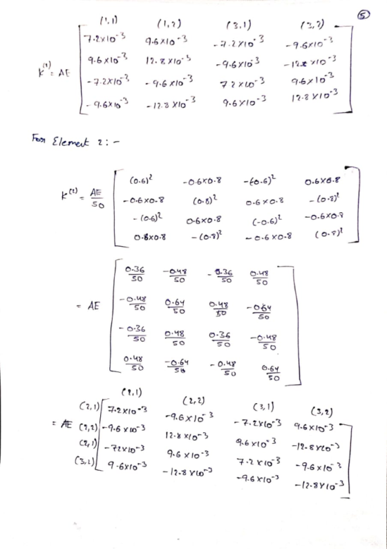
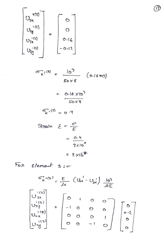
 A plane truss element is shown in Figure 4, All elements have cross-sectional area of A = 8 in, and elastic modulus of E-2 x 10° psi. Use long-hand solution 6. 6.(a). Solve for the unknown displacements. 6.(b). Solve for strains and stresses in al 3 elements. Show your work and follow the finite element method matrix formulation we have covered in lectures. 4 5 kip 10 240 ft 30 ft30 ft Figure 4.
A plane truss element is shown...
A plane truss element is shown in Figure 4, All elements have cross-sectional area of A = 8 in, and elastic modulus of E-2 x 10° psi. Use long-hand solution 6. 6.(a). Solve for the unknown displacements. 6.(b). Solve for strains and stresses in al 3 elements. Show your work and follow the finite element method matrix formulation we have covered in lectures. 4 5 kip 10 240 ft 30 ft30 ft Figure 4.
A plane truss element is shown...
Problem 1 The truss (all joints are pinned) structure in figure 1 is made of members with cross s...
 We were unable to transcribe this imageProblem 1 The truss (all joints are pinned) structure in figure 1 is made of members with cross sectional area A = 1 in, with a linear elastic, homogeneous, isotropic material with an elastic modulus. E-10E6 psi and a coefficient of thermal expansion, α-6E-6 °F-ι. The structure starts out at a uniform temperature of 65°F and is raised to a final temperature of 120°F while being subjected to a concentrated load Po- 5,000 lbs...
For the truss shown in the below figure, determine the stifness matrix for each truss element,...
 For the truss shown in the below figure, determine the stifness
matrix for each truss element, the stiffness matrix for entire
truss, the displacements at nodes 1 through 4, and the force in
elements 1 through 5. Also, determine the force in each element.
Let A = 3 in2, E = 30 x 106
psi for all elements.
8 kips 8 kips 10 ft. 3 4 2 トー-10ft.-*-10 ft.
For the truss shown in the below figure, determine the stifness
matrix for each truss element, the stiffness matrix for entire
truss, the displacements at nodes 1 through 4, and the force in
elements 1 through 5. Also, determine the force in each element.
Let A = 3 in2, E = 30 x 106
psi for all elements.
8 kips 8 kips 10 ft. 3 4 2 トー-10ft.-*-10 ft.
Problem 2: a. For the plane truss shown in Figure 2, determine the nodal displacements, the element forces and stresses, and the support reactions. All elements have E-70 GPa and A-25 cm 100 k...
 Problem 2: a. For the plane truss shown in Figure 2, determine the nodal displacements, the element forces and stresses, and the support reactions. All elements have E-70 GPa and A-25 cm 100 kN 50 kN 50 kN 4 4 6 Figure 2. Plane Truss
Problem 2: a. For the plane truss shown in Figure 2, determine the nodal displacements, the element forces and stresses, and the support reactions. All elements have E-70 GPa and A-25 cm 100 kN 50...
Problem 2: a. For the plane truss shown in Figure 2, determine the nodal displacements, the element forces and stresses, and the support reactions. All elements have E-70 GPa and A-25 cm 100 kN 50 kN 50 kN 4 4 6 Figure 2. Plane Truss
Problem 2: a. For the plane truss shown in Figure 2, determine the nodal displacements, the element forces and stresses, and the support reactions. All elements have E-70 GPa and A-25 cm 100 kN 50...
A plane structure consists of three truss elements connected to four nodes, as shown below. All t...
 A plane structure consists of three truss elements connected to four nodes, as shown below. All trusses have cross sectional area A -7.104 m2 and elastic modulus E = 210 GPa. The length of each truss element is L = 1 m. A point force, P -5 kN, is acting on node 4 L/2 3.1 Calculate the displacements at the nodes 3.2 Calculate the reaction forces 3.3 Calculate the stress in each bar
A plane structure consists of three truss...
A plane structure consists of three truss elements connected to four nodes, as shown below. All trusses have cross sectional area A -7.104 m2 and elastic modulus E = 210 GPa. The length of each truss element is L = 1 m. A point force, P -5 kN, is acting on node 4 L/2 3.1 Calculate the displacements at the nodes 3.2 Calculate the reaction forces 3.3 Calculate the stress in each bar
A plane structure consists of three truss...
Grid 4 Grid 3 Po 15 in Grid 1 Grid 2 10 in Figure 1: Problem...
 Grid 4 Grid 3 Po 15 in Grid 1 Grid 2 10 in Figure 1: Problem 1 Schematic Problem 1 The truss (all joints are pinned) structure in figure 1 is made of members with cross sectional area A- 1 in2, with a linear elastic, homogeneous, isotropic material with an elastic modulus, E, 10E6 psi and a coefficient of thermal expansion. α-6E-6 op-1. The structure starts out at a uniform temperature of 65°F and is raised to a final temperature...
Solve all problems using the finite element stiffness method. For the rigid frame shown in Figure...
 Solve all problems using the finite element stiffness method. For the rigid frame shown in Figure P5-4, determine (1) the nodal displacements and rotation at node 4, (2) the reactions, and (3) the forces in each element. Then check equilibrium at node 4. Finally, draw the shear force and bending moment diagrams for each element. LetE 30 x 103 ksi, A = 8 in,2 , and 1-800 in.4 for all elements. 20 kip 25 ft 25 ft- 40 ft 20...
Solve all problems using the finite element stiffness method. For the rigid frame shown in Figure P5-4, determine (1) the nodal displacements and rotation at node 4, (2) the reactions, and (3) the fo...
 Solve all problems using the finite element stiffness method. For the rigid frame shown in Figure P5-4, determine (1) the nodal displacements and rotation at node 4, (2) the reactions, and (3) the forces in each element. Then check equilibrium at node 4 Finally, draw the shear force and bending moment diagrams for each element. Let E 30x 103 ksi, A 8 in2, and I 800 in.4 for all elements. 20 kip 25 ft 25 ft 40 ft Figure P5-4...
Finite Element Method 5.17 Displacements of the three-member truss shown are confined to the plane of...
 Finite Element Method
5.17 Displacements of the three-member truss shown are confined to the plane of the figure, and points 1, 2 and 3 are fixed to the stationary rim. All members have the same A, E, and L a) Obtain the 2x2 stiffness matrix that operates on the horizontal and vertical degrees of freedom of the central node. b) Obtain the corresponding global force vector c) Solve for the displacements and for axial stress in member (2-4), when the...
Finite Element Method
5.17 Displacements of the three-member truss shown are confined to the plane of the figure, and points 1, 2 and 3 are fixed to the stationary rim. All members have the same A, E, and L a) Obtain the 2x2 stiffness matrix that operates on the horizontal and vertical degrees of freedom of the central node. b) Obtain the corresponding global force vector c) Solve for the displacements and for axial stress in member (2-4), when the...
Plane truss
 The lower-right joint of the three-member plane truss shown in Figure 2 is supportedby a skew roller. The truss members are of a solid circular cross section having diameterd D 25 mm and elastic modulus E D 50 GPa. The force P D 70 kN is applied to theunconstrained joint. Number the nodes and elements, and solve for unknown nodaldisplacements and reaction forces using:a) Master-slave method,b) Penalty element method,c) Lagrange multiplier method.
 A plane truss element is shown in Figure 4, All elements have cross-sectional area of A = 8 in, and elastic modulus of E-2 x 10° psi. Use long-hand solution 6. 6.(a). Solve for the unknown displacements. 6.(b). Solve for strains and stresses in al 3 elements. Show your work and follow the finite element method matrix formulation we have covered in lectures. 4 5 kip 10 240 ft 30 ft30 ft Figure 4.
A plane truss element is shown...
A plane truss element is shown in Figure 4, All elements have cross-sectional area of A = 8 in, and elastic modulus of E-2 x 10° psi. Use long-hand solution 6. 6.(a). Solve for the unknown displacements. 6.(b). Solve for strains and stresses in al 3 elements. Show your work and follow the finite element method matrix formulation we have covered in lectures. 4 5 kip 10 240 ft 30 ft30 ft Figure 4.
A plane truss element is shown...
 We were unable to transcribe this imageProblem 1 The truss (all joints are pinned) structure in figure 1 is made of members with cross sectional area A = 1 in, with a linear elastic, homogeneous, isotropic material with an elastic modulus. E-10E6 psi and a coefficient of thermal expansion, α-6E-6 °F-ι. The structure starts out at a uniform temperature of 65°F and is raised to a final temperature of 120°F while being subjected to a concentrated load Po- 5,000 lbs...
 For the truss shown in the below figure, determine the stifness
matrix for each truss element, the stiffness matrix for entire
truss, the displacements at nodes 1 through 4, and the force in
elements 1 through 5. Also, determine the force in each element.
Let A = 3 in2, E = 30 x 106
psi for all elements.
8 kips 8 kips 10 ft. 3 4 2 トー-10ft.-*-10 ft.
For the truss shown in the below figure, determine the stifness
matrix for each truss element, the stiffness matrix for entire
truss, the displacements at nodes 1 through 4, and the force in
elements 1 through 5. Also, determine the force in each element.
Let A = 3 in2, E = 30 x 106
psi for all elements.
8 kips 8 kips 10 ft. 3 4 2 トー-10ft.-*-10 ft.
 Problem 2: a. For the plane truss shown in Figure 2, determine the nodal displacements, the element forces and stresses, and the support reactions. All elements have E-70 GPa and A-25 cm 100 kN 50 kN 50 kN 4 4 6 Figure 2. Plane Truss
Problem 2: a. For the plane truss shown in Figure 2, determine the nodal displacements, the element forces and stresses, and the support reactions. All elements have E-70 GPa and A-25 cm 100 kN 50...
Problem 2: a. For the plane truss shown in Figure 2, determine the nodal displacements, the element forces and stresses, and the support reactions. All elements have E-70 GPa and A-25 cm 100 kN 50 kN 50 kN 4 4 6 Figure 2. Plane Truss
Problem 2: a. For the plane truss shown in Figure 2, determine the nodal displacements, the element forces and stresses, and the support reactions. All elements have E-70 GPa and A-25 cm 100 kN 50...
 A plane structure consists of three truss elements connected to four nodes, as shown below. All trusses have cross sectional area A -7.104 m2 and elastic modulus E = 210 GPa. The length of each truss element is L = 1 m. A point force, P -5 kN, is acting on node 4 L/2 3.1 Calculate the displacements at the nodes 3.2 Calculate the reaction forces 3.3 Calculate the stress in each bar
A plane structure consists of three truss...
A plane structure consists of three truss elements connected to four nodes, as shown below. All trusses have cross sectional area A -7.104 m2 and elastic modulus E = 210 GPa. The length of each truss element is L = 1 m. A point force, P -5 kN, is acting on node 4 L/2 3.1 Calculate the displacements at the nodes 3.2 Calculate the reaction forces 3.3 Calculate the stress in each bar
A plane structure consists of three truss...
 Grid 4 Grid 3 Po 15 in Grid 1 Grid 2 10 in Figure 1: Problem 1 Schematic Problem 1 The truss (all joints are pinned) structure in figure 1 is made of members with cross sectional area A- 1 in2, with a linear elastic, homogeneous, isotropic material with an elastic modulus, E, 10E6 psi and a coefficient of thermal expansion. α-6E-6 op-1. The structure starts out at a uniform temperature of 65°F and is raised to a final temperature...
 Solve all problems using the finite element stiffness method. For the rigid frame shown in Figure P5-4, determine (1) the nodal displacements and rotation at node 4, (2) the reactions, and (3) the forces in each element. Then check equilibrium at node 4. Finally, draw the shear force and bending moment diagrams for each element. LetE 30 x 103 ksi, A = 8 in,2 , and 1-800 in.4 for all elements. 20 kip 25 ft 25 ft- 40 ft 20...
 Solve all problems using the finite element stiffness method. For the rigid frame shown in Figure P5-4, determine (1) the nodal displacements and rotation at node 4, (2) the reactions, and (3) the forces in each element. Then check equilibrium at node 4 Finally, draw the shear force and bending moment diagrams for each element. Let E 30x 103 ksi, A 8 in2, and I 800 in.4 for all elements. 20 kip 25 ft 25 ft 40 ft Figure P5-4...
 Finite Element Method
5.17 Displacements of the three-member truss shown are confined to the plane of the figure, and points 1, 2 and 3 are fixed to the stationary rim. All members have the same A, E, and L a) Obtain the 2x2 stiffness matrix that operates on the horizontal and vertical degrees of freedom of the central node. b) Obtain the corresponding global force vector c) Solve for the displacements and for axial stress in member (2-4), when the...
Finite Element Method
5.17 Displacements of the three-member truss shown are confined to the plane of the figure, and points 1, 2 and 3 are fixed to the stationary rim. All members have the same A, E, and L a) Obtain the 2x2 stiffness matrix that operates on the horizontal and vertical degrees of freedom of the central node. b) Obtain the corresponding global force vector c) Solve for the displacements and for axial stress in member (2-4), when the...
Most questions answered within 3 hours.
-
A coach uses a new technique to train gymnasts. Seven
gymnasts were randomly selected and their...
asked 1 hour ago -
While rotating the tires on your car you notice a rock [mass =
0.1 Kg] stuck...
asked 3 hours ago -
Using MARS simulator, write MIPS programs according to
the following scenarios: Receive a positive integer number...
asked 5 hours ago -
An object in front of a concave mirror has a real image that is
11.5 cm...
asked 5 hours ago -
Consider the reaction, C3 H8 + O2 --> CO2 + H2O. How many
moles of O2...
asked 7 hours ago -
You and your opponent both roll a fair die. If you both roll the
same number,...
asked 7 hours ago -
In a study of the accuracy of fast food drive-through orders,
Restaurant A had 257 accurate...
asked 7 hours ago -
Identify and describe in detail the four categories of
institutions that could be included in a...
asked 7 hours ago -
In python
class Customer:
def __init__(self, customer_id, last_name, first_name, phone_number, address):
self._customer_id = int(customer_id)
self._last_name =...
asked 7 hours ago -
What is an example of a limitation in implementing a new
ERP system and how it...
asked 7 hours ago -
In a section of 9.7cm of an artery with a radius of 2.6mm there
is a...
asked 7 hours ago -
the two carboxylic acid groups of aspartic acid have different
acidities with pKa values of 2.1...
asked 7 hours ago