
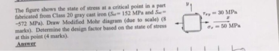
The figure shows the state of stress at a critical point in a part fabricated from Class 20 gray cast iron (S 152 MPa and S -572 MPa). Draw Modified Mohr diagram (due to scale) (8 marks). Determine the design factor based on the state of stress at this point (4 marks). Answer y 30 MP Oz = 50 MPa
Homework Answers
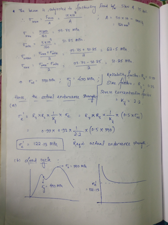
The problem is that of the fluctuating loads. Hence, the mean and variable forces can be calculated from the data given, and hence, the mean and variable stresses are calculated.
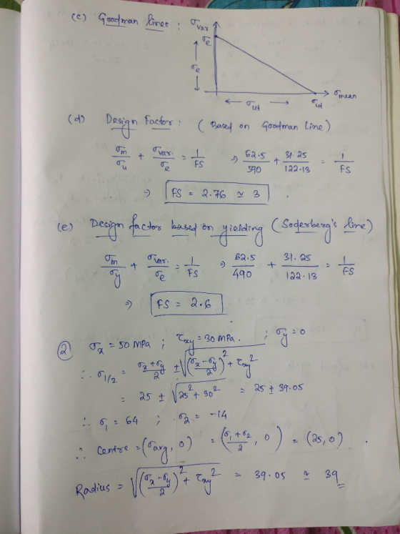
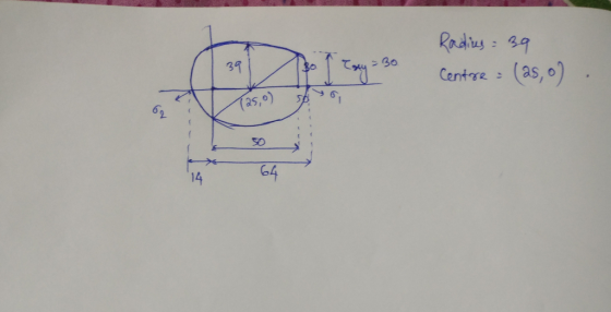
The endurance strength can be expressed as the product of the reliability , size factor, and the inverse of the theoretical stress concentration factor, with that of the endurance limit. If endurance limit is not given directly, then half of the ultimate limit is taken into consideration. The actual endurance limit can be hence calculated by the method illustrated in the pictures enclosed. Kindly check the same for other detailed solution as well.
Thank You
Add Answer to:
Question 3 128 Marks 2 rectangular beam shown in the figure is subjected to a fluctuating axial f...
Question 2 The steel cantilever beam shown here is subjected to a fluctuating transverse force, P,...
 Question 2 The steel cantilever beam shown here is subjected to a fluctuating transverse force, P, The part is solid and cylindrical with a diameter of 30 mm The bar material is machined and made of AISI ASTM Class 40 Steel machine finish. It will be used at room temperature. A reliability of 95% is desired for the part. a. Find the Design Endurance Limit (S.) b. Find the Endurance Strength at 100,000
Question 1 A flat leaf spring made from AISI 1020 cold drawn steel has fluctuating stresses between the maximum stre...
 Question 1 A flat leaf spring made from AISI 1020 cold drawn steel has fluctuating stresses between the maximum stress, Smar of 360 MPa and minimum stress, Smn of 160 MPa; applied for a duration of 8 (10) cycles. The AISI 1020 CD material has a fully corrected endurance strength of Sa 5 175 MPa, yield strength, S, of 390 MPa and ultimate strength, S of 470 MPa. Assume that the fatigue strength fraction, f of 0.9 Using Miner's method,...
In an application, an Acme-threaded power screws is to be designed to raise a maximum load of 50 ...
 SOLVE ALL , Show details clear and orgnaized
In an application, an Acme-threaded power screws is to be designed to raise a maximum load of 50 kN. (a) Select a satisfactory screw from the Table on the basis of tensile strength, limiting the tensile stress to 70 MPa (2 marks). (b) Then determine the required thickness of the nut that to limit the shear stress in the threads to 35 MPa (2 marks). (c) For the screw thus designed, check...
SOLVE ALL , Show details clear and orgnaized
In an application, an Acme-threaded power screws is to be designed to raise a maximum load of 50 kN. (a) Select a satisfactory screw from the Table on the basis of tensile strength, limiting the tensile stress to 70 MPa (2 marks). (b) Then determine the required thickness of the nut that to limit the shear stress in the threads to 35 MPa (2 marks). (c) For the screw thus designed, check...
A rectangular beam is subjected to the loadings shown in Figure Q.16(a) has cross section of...
 A rectangular beam is subjected to the loadings shown in Figure Q.16(a) has cross section of 100 mm x 300 mm as shown in Figure Q.16(b). An axial load of 5 kN is applied along the centroid of the cross-section at one end of the beam. Compute the normal stress and shear stress at point P through the cut-section of P in the beam. [15 marks] у 10 kN/m P Ž 5 KN --- 00 P k 3 m -...
PLEASE MAKE SURE THE ANSWERS MATCH THE ONES GIVEN BETWEEN PARENTHESES 1. Fluctuating loading. The cold-drawn...
 PLEASE MAKE SURE THE ANSWERS MATCH THE ONES GIVEN BETWEEN
PARENTHESES
1. Fluctuating loading. The cold-drawn AISI 1040 steel bar (S590 MPa, S 490 MPa) shown in the figure is subjected to the following different cyclic loading conditions. Estimate the fatigue factor of safety based on achieving infinite life (use Modified Goodman method) and the yielding factor of safety. If infinite life is not predicted, estimate the number of cycles to failure. The fatigue strength modification factor f 0.87. For...
PLEASE MAKE SURE THE ANSWERS MATCH THE ONES GIVEN BETWEEN
PARENTHESES
1. Fluctuating loading. The cold-drawn AISI 1040 steel bar (S590 MPa, S 490 MPa) shown in the figure is subjected to the following different cyclic loading conditions. Estimate the fatigue factor of safety based on achieving infinite life (use Modified Goodman method) and the yielding factor of safety. If infinite life is not predicted, estimate the number of cycles to failure. The fatigue strength modification factor f 0.87. For...
Figure Q3 shows a simply supported beam carrying a point load. The beam hasa rectangular hollow...
 Figure Q3 shows a simply supported beam carrying a point load. The beam hasa rectangular hollow steel section as shown in Figure Q3. a. Calculate the second moment of area of the section about the horizontal (10 marks) centroidal axis. Calculate the maximum allowable value of the point load Wif the elastic bending (15 marks) b. stress in the beam is to be limited to 250 MPa. c. Calculate the maximum shear stress at q-q in the beam when the...
The beam shown in the figure is loaded with a distributed dead load G (including self-weight)...
 The beam shown in the figure is loaded with a distributed dead load G (including self-weight) and a distributed live load Q. Additionally, a point load Pq is acting on the structure. aPa d. The following values are used for this singly reinforced beam 29 MPa 500 MPa A 280 mm Ag 1350 mm Po 90 kN d 540 mm G 12 kN/m d. 60 mm .Q26 kN/m . b.350 mm I 7m do load factor for Pa .S300 mm...
Design Problem: : (20 marks) Flr a safety factor of 2, find the safe load that...
 Design Problem: : (20 marks) Flr a safety factor of 2, find the safe load that the AISI 1020 beam, fixed at both ends (1o mm widex mm deep and span 2m) can carry: 180 (1) by elastic analysis, with the factor of safety based on yield, and, (2) by plastic design. (note: AISI 1020 Steel: yield stress 250 MPa, )
The cantilever beam shown in the figure is subjected to a concentrated load at point B....
 The cantilever beam shown in the figure is subjected to a concentrated load at point B. The stresses acting at point H on the beam are to be determined. H Cross section For this analysis, use the following values: Beam and Load. a = 1.75 m b=0.30 m @= 60 degrees P = 25 KN Cross-sectional Dimensions d=250 mm bp = 125 mm ty=7 mm tw = 7 mm C= 30 mm (Note: The load P applied at Bacts in...
Task 1: (50 Marks) Cross section of a reinforced concrete beam is shown in Figure 1....
 Task 1: (50 Marks) Cross section of a reinforced concrete beam is shown in Figure 1. The following shear forces have been calculated due to Dead Load and Live Load at the support: VDL = 150 kN, ViL = 200 kN. Design the shear reinforcement for the ultimate shear force. Use No. 10 bars for shear reinforcement Assume "fe, = 28 MPa, fyt-420 MPa, b = 300 mm, d = 750 mm, h = 800 mm Figure 1. Beam cross-section
 Question 2 The steel cantilever beam shown here is subjected to a fluctuating transverse force, P, The part is solid and cylindrical with a diameter of 30 mm The bar material is machined and made of AISI ASTM Class 40 Steel machine finish. It will be used at room temperature. A reliability of 95% is desired for the part. a. Find the Design Endurance Limit (S.) b. Find the Endurance Strength at 100,000
 Question 1 A flat leaf spring made from AISI 1020 cold drawn steel has fluctuating stresses between the maximum stress, Smar of 360 MPa and minimum stress, Smn of 160 MPa; applied for a duration of 8 (10) cycles. The AISI 1020 CD material has a fully corrected endurance strength of Sa 5 175 MPa, yield strength, S, of 390 MPa and ultimate strength, S of 470 MPa. Assume that the fatigue strength fraction, f of 0.9 Using Miner's method,...
 SOLVE ALL , Show details clear and orgnaized
In an application, an Acme-threaded power screws is to be designed to raise a maximum load of 50 kN. (a) Select a satisfactory screw from the Table on the basis of tensile strength, limiting the tensile stress to 70 MPa (2 marks). (b) Then determine the required thickness of the nut that to limit the shear stress in the threads to 35 MPa (2 marks). (c) For the screw thus designed, check...
SOLVE ALL , Show details clear and orgnaized
In an application, an Acme-threaded power screws is to be designed to raise a maximum load of 50 kN. (a) Select a satisfactory screw from the Table on the basis of tensile strength, limiting the tensile stress to 70 MPa (2 marks). (b) Then determine the required thickness of the nut that to limit the shear stress in the threads to 35 MPa (2 marks). (c) For the screw thus designed, check...
 A rectangular beam is subjected to the loadings shown in Figure Q.16(a) has cross section of 100 mm x 300 mm as shown in Figure Q.16(b). An axial load of 5 kN is applied along the centroid of the cross-section at one end of the beam. Compute the normal stress and shear stress at point P through the cut-section of P in the beam. [15 marks] у 10 kN/m P Ž 5 KN --- 00 P k 3 m -...
 PLEASE MAKE SURE THE ANSWERS MATCH THE ONES GIVEN BETWEEN
PARENTHESES
1. Fluctuating loading. The cold-drawn AISI 1040 steel bar (S590 MPa, S 490 MPa) shown in the figure is subjected to the following different cyclic loading conditions. Estimate the fatigue factor of safety based on achieving infinite life (use Modified Goodman method) and the yielding factor of safety. If infinite life is not predicted, estimate the number of cycles to failure. The fatigue strength modification factor f 0.87. For...
PLEASE MAKE SURE THE ANSWERS MATCH THE ONES GIVEN BETWEEN
PARENTHESES
1. Fluctuating loading. The cold-drawn AISI 1040 steel bar (S590 MPa, S 490 MPa) shown in the figure is subjected to the following different cyclic loading conditions. Estimate the fatigue factor of safety based on achieving infinite life (use Modified Goodman method) and the yielding factor of safety. If infinite life is not predicted, estimate the number of cycles to failure. The fatigue strength modification factor f 0.87. For...
 Figure Q3 shows a simply supported beam carrying a point load. The beam hasa rectangular hollow steel section as shown in Figure Q3. a. Calculate the second moment of area of the section about the horizontal (10 marks) centroidal axis. Calculate the maximum allowable value of the point load Wif the elastic bending (15 marks) b. stress in the beam is to be limited to 250 MPa. c. Calculate the maximum shear stress at q-q in the beam when the...
 The beam shown in the figure is loaded with a distributed dead load G (including self-weight) and a distributed live load Q. Additionally, a point load Pq is acting on the structure. aPa d. The following values are used for this singly reinforced beam 29 MPa 500 MPa A 280 mm Ag 1350 mm Po 90 kN d 540 mm G 12 kN/m d. 60 mm .Q26 kN/m . b.350 mm I 7m do load factor for Pa .S300 mm...
 Design Problem: : (20 marks) Flr a safety factor of 2, find the safe load that the AISI 1020 beam, fixed at both ends (1o mm widex mm deep and span 2m) can carry: 180 (1) by elastic analysis, with the factor of safety based on yield, and, (2) by plastic design. (note: AISI 1020 Steel: yield stress 250 MPa, )
 The cantilever beam shown in the figure is subjected to a concentrated load at point B. The stresses acting at point H on the beam are to be determined. H Cross section For this analysis, use the following values: Beam and Load. a = 1.75 m b=0.30 m @= 60 degrees P = 25 KN Cross-sectional Dimensions d=250 mm bp = 125 mm ty=7 mm tw = 7 mm C= 30 mm (Note: The load P applied at Bacts in...
 Task 1: (50 Marks) Cross section of a reinforced concrete beam is shown in Figure 1. The following shear forces have been calculated due to Dead Load and Live Load at the support: VDL = 150 kN, ViL = 200 kN. Design the shear reinforcement for the ultimate shear force. Use No. 10 bars for shear reinforcement Assume "fe, = 28 MPa, fyt-420 MPa, b = 300 mm, d = 750 mm, h = 800 mm Figure 1. Beam cross-section
Most questions answered within 3 hours.
-
Given that many conflict are the result of different parties having
different interests, is it possible...
asked 20 seconds ago -
A 750 g block can slide uniformly along the horizontal track
when a string attached to...
asked 3 minutes ago -
In 2017, Juan entered into a contract to write a book. The
publisher advanced Juan $50,000,...
asked 16 minutes ago -
Determine the number of kinds of protons in each molecule (w/
respect to NMR spectroscopy). Drawing...
asked 27 minutes ago -
A jeweler whose near point is 68 cm from his eye uses a
magnifying glass as...
asked 25 minutes ago -
A company wants to determine how many units of each of two
products, A and B,...
asked 29 minutes ago -
The blood pressure of a person changes throughout the day.
Suppose the systolic blood pressure of...
asked 37 minutes ago -
A chemistry student desired to study sulfur. Sulfur exhibited
the following characteristics with oxygen:
(a) It...
asked 33 minutes ago -
An Atwood machine is constructed of a solid-disk frictionless
pulley of mass m3 and radius R....
asked 35 minutes ago -
what are the advantages of lanthanum hexaboride over tungsten
filament for electron emission
what is the...
asked 37 minutes ago -
Question 5
Your uncle offers to sell you his vintage Rolls Royce. He
suggests a payment...
asked 41 minutes ago -
Quality grading of beef products as Prime, Choice, Select. What
type of data?
A) ratio
B)...
asked 51 minutes ago