
Homework Answers


Add Answer to:
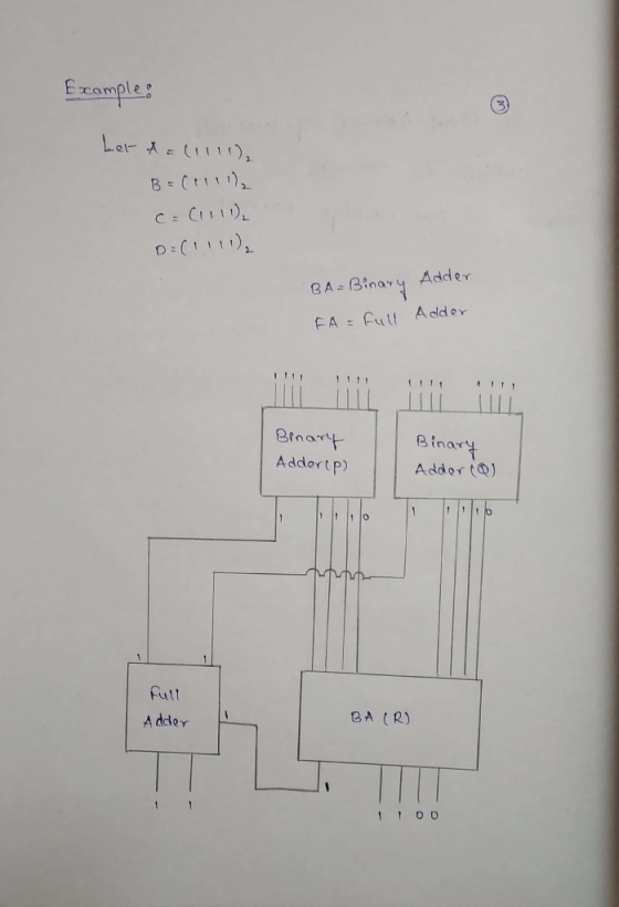
[Paperl (10 pts.) Design a circuit that takes in four 4-bit unsigned numbers, A (A3..Ao), B (B3.....
design and build a 4 bit binary multiplier that multiplies two 4 bit unsigned positive numbers...
design and build a 4 bit binary multiplier that multiplies two 4 bit unsigned positive numbers to generate a 8 bit unsigned positive number. using full adders. do not use 4 bit multiplier chip. use truth table, karnaugh map and simplified output expression of the circuit.
11. Refer to figure 2 to complete the table given. A3-AO B3-BO x S4-SO (5 bits)...
 11. Refer to figure 2 to complete the table given. A3-AO B3-BO x S4-SO (5 bits) BCD sum (4 bits) 0101 0010 0111 0100 1000 1001 1001 0011 B, B2, Bo BCD code group CA 4-bit parallel dder (74LS93) Ca, carry from + lower position adder SA S; S S, S. Az Az A, A BCD code group Carry to next BCD adder X 74LS32 74LSOB Correction Logic 74LS32 Co = 0 CA not Leed 4-bit parallel addar 174L983) TIL...
The following is a diagram of a series of 1-bit full adders that will be used...
 The following is a diagram of a series of 1-bit full adders that will be used to add the binary numbers 1011 (A) and 1111 (B) A3 B3 A2 B2 Ai B1 Ао Во 1-bit 1-bit 1-bit 1-bit Full Full Full Full C4 Adder C3 Adder C2 Adder C1 Adder Co Fig 1 Type the correct binary value into each box: Note: you should only enter one digit in each box.
2. Build an 8-bit comparator that compares unsigned numbers A = a7 ao and B =...
 2. Build an 8-bit comparator that compares unsigned numbers A = a7 ao and B = b1" . bo and outputs 1 if A > B . First build a smaller unit (using K-map) with logic gates that compares two bit numbers X=x1x0 and Y =y,yo. Then, use sufficient number of these elements with required additional gates to build the final circuit.
multiply highligted value by four and please explain Given: A 4-bit adder is implemented in a...
 multiply highligted value by
four and please explain
Given: A 4-bit adder is implemented in a carry ripple style as shown in the figure below. B3 A3 B2 A2 B1A1 BO AO c3 c1 FA FA FA FA CO='1' Sought: Please calculate the output carries for each full adder (FA) using A=0x01 and B=0x04 It is required to show ALL incremental steps of the solution, then record each the final results in the table below. C4 C2 ci
multiply highligted value by
four and please explain
Given: A 4-bit adder is implemented in a carry ripple style as shown in the figure below. B3 A3 B2 A2 B1A1 BO AO c3 c1 FA FA FA FA CO='1' Sought: Please calculate the output carries for each full adder (FA) using A=0x01 and B=0x04 It is required to show ALL incremental steps of the solution, then record each the final results in the table below. C4 C2 ci
number 4 and 5 please! PROBLEM STATEMENT A logic circuit is needed to add multi-bit binary...
 number 4 and 5 please!
PROBLEM STATEMENT A logic circuit is needed to add multi-bit binary numbers. A 2-level circuit that would add two four-bit numbers would have 9 inputs and five outputs. Although a 2-level SOP or POS circuit theoretically would be very fast, it has numerous drawbacks that make it impractical. The design would be very complex in terms of the number of logic gates. The number of inputs for each gate would challenge target technologies. Testing would...
number 4 and 5 please!
PROBLEM STATEMENT A logic circuit is needed to add multi-bit binary numbers. A 2-level circuit that would add two four-bit numbers would have 9 inputs and five outputs. Although a 2-level SOP or POS circuit theoretically would be very fast, it has numerous drawbacks that make it impractical. The design would be very complex in terms of the number of logic gates. The number of inputs for each gate would challenge target technologies. Testing would...
(1) How do you design a 4-bit adder (i.e. C = A + B) using 1-bit...
(1) How do you design a 4-bit adder (i.e. C = A + B) using 1-bit full adders, and with circuits detecting if results are negative OR results are zero. (Note: output 1 when the if-condition is true; otherwise, output 0.)
You are to design a circuit that calculates the Hamming distance between two 5-bit numbers. It...
You are to design a circuit that calculates the Hamming distance between two 5-bit numbers. It takes two 5-bit binary numbers A4 A3 A2 A1 A0 and B4 B3B 2B1 B0 as inputs and returns the number of bits that are different between the two numbers as the 3-bit binary output O2 O1 O0. For example: *If the two input numbers were 10111 and 00001 then the output would be 011 as there are 3 bits different between them. *If...
Introduction: This experiment studies the design of an 8-bit adder/subtractor circuit using VHDL capture. The experiment...
 Introduction: This experiment studies the design of an 8-bit adder/subtractor circuit using VHDL capture. The experiment investigates the implementation of addition and subtraction operations with circuits. This lab uses the virtual simulation environment to validate the design practically in the FPGA board. Equipment: • This experiment requires Quartus Prime and the Intel's DE2-115 FPGA board. • All students should have the Intel QP and ModelSim-Intel-Starter-Edition softwares installed in personal computers. • VPN connection to UNB Network and remote desktop software...
Design a combinational circuit which compares two 4-bit unsigned numbers A and B. The circuit should...
Design a combinational circuit which compares two 4-bit unsigned numbers A and B. The circuit should have one output X such that X = 1 whenever A>B and X = 0 whenever A?B. You may use any MSI modules as well as any other gates.
 11. Refer to figure 2 to complete the table given. A3-AO B3-BO x S4-SO (5 bits) BCD sum (4 bits) 0101 0010 0111 0100 1000 1001 1001 0011 B, B2, Bo BCD code group CA 4-bit parallel dder (74LS93) Ca, carry from + lower position adder SA S; S S, S. Az Az A, A BCD code group Carry to next BCD adder X 74LS32 74LSOB Correction Logic 74LS32 Co = 0 CA not Leed 4-bit parallel addar 174L983) TIL...
 The following is a diagram of a series of 1-bit full adders that will be used to add the binary numbers 1011 (A) and 1111 (B) A3 B3 A2 B2 Ai B1 Ао Во 1-bit 1-bit 1-bit 1-bit Full Full Full Full C4 Adder C3 Adder C2 Adder C1 Adder Co Fig 1 Type the correct binary value into each box: Note: you should only enter one digit in each box.
 2. Build an 8-bit comparator that compares unsigned numbers A = a7 ao and B = b1" . bo and outputs 1 if A > B . First build a smaller unit (using K-map) with logic gates that compares two bit numbers X=x1x0 and Y =y,yo. Then, use sufficient number of these elements with required additional gates to build the final circuit.
 multiply highligted value by
four and please explain
Given: A 4-bit adder is implemented in a carry ripple style as shown in the figure below. B3 A3 B2 A2 B1A1 BO AO c3 c1 FA FA FA FA CO='1' Sought: Please calculate the output carries for each full adder (FA) using A=0x01 and B=0x04 It is required to show ALL incremental steps of the solution, then record each the final results in the table below. C4 C2 ci
multiply highligted value by
four and please explain
Given: A 4-bit adder is implemented in a carry ripple style as shown in the figure below. B3 A3 B2 A2 B1A1 BO AO c3 c1 FA FA FA FA CO='1' Sought: Please calculate the output carries for each full adder (FA) using A=0x01 and B=0x04 It is required to show ALL incremental steps of the solution, then record each the final results in the table below. C4 C2 ci
 number 4 and 5 please!
PROBLEM STATEMENT A logic circuit is needed to add multi-bit binary numbers. A 2-level circuit that would add two four-bit numbers would have 9 inputs and five outputs. Although a 2-level SOP or POS circuit theoretically would be very fast, it has numerous drawbacks that make it impractical. The design would be very complex in terms of the number of logic gates. The number of inputs for each gate would challenge target technologies. Testing would...
number 4 and 5 please!
PROBLEM STATEMENT A logic circuit is needed to add multi-bit binary numbers. A 2-level circuit that would add two four-bit numbers would have 9 inputs and five outputs. Although a 2-level SOP or POS circuit theoretically would be very fast, it has numerous drawbacks that make it impractical. The design would be very complex in terms of the number of logic gates. The number of inputs for each gate would challenge target technologies. Testing would...
 Introduction: This experiment studies the design of an 8-bit adder/subtractor circuit using VHDL capture. The experiment investigates the implementation of addition and subtraction operations with circuits. This lab uses the virtual simulation environment to validate the design practically in the FPGA board. Equipment: • This experiment requires Quartus Prime and the Intel's DE2-115 FPGA board. • All students should have the Intel QP and ModelSim-Intel-Starter-Edition softwares installed in personal computers. • VPN connection to UNB Network and remote desktop software...
Most questions answered within 3 hours.
-
3. Gains from trade
Consider two neighbouring island countries called Euphoria and
Contente. They each have...
asked 18 minutes ago -
A business executive has the option to invest money in two
plans: Plan A guarantees that...
asked 2 hours ago -
Hello, can someone please help me answer this question?
How much heat is absorbed by a...
asked 2 hours ago -
. A marketing researcher conducted a survey of 25 shoppers
randomly selected at the local mall...
asked 2 hours ago -
Create an comprehensive response to the
following:
Antimicrobial agents work on a multitude of microbes (bacteria,...
asked 2 hours ago -
6.13 LAB: Step counter. Section 6.3.
A pedometer treats walking 2,000 steps as walking 1 mile....
asked 2 hours ago -
(14.2) A block of mass m = 10 kg riding on a frictionless
horizontal plane is...
asked 2 hours ago -
Use any search engine to search for articles about Starbucks
partnership with Tata Companies in India...
asked 2 hours ago -
Let’s say that for some reason Bank Excess Reserves suddenly
increase sharply. What effect would this...
asked 3 hours ago -
Given:
Curent Assets: $600,000
Total Assets: $2,600,000
Current Liabilities: $500,000
Total Liabilities: $1,700,000
What is the...
asked 3 hours ago -
1. What is a “Bankster”? What is insider trading? Why is it
illegal?
2. What is...
asked 3 hours ago -
A transverse wave on a cord is given by
D(x,t)=0.18sin(2.7x−61.0t), where Dand x are in m...
asked 3 hours ago