
Homework Answers
Add Answer to:
Introduction: This experiment studies the design of an 8-bit adder/subtractor circuit using VHDL capture. The experiment...
4. Design a 4-bit Adder / Subtractor. Follow the steps given below. (a) Write the VHDL...
 4. Design a 4-bit Adder / Subtractor. Follow the steps given below. (a) Write the VHDL code for a 1-bit Full Adder. The VHDL code must include an entity and an architecture. (b) Draw the circuit diagram for a 4-bit Adder / Subtractor. The circuit diagram may include the following logic elements: 1-bit Full Adders (shown as a block with inputs and outputs) Any 2-input logic gates Multiplexers Do not draw the logic circuit for the 1-bit Full Adder.
Construct the 8-bit ripple-carry adder/subtractor for signed integers. Negative numbers are in th...
 Construct the 8-bit ripple-carry adder/subtractor for signed integers. Negative numbers are in the 2's complement form. The circuit has inputs X(7:0), Y(7:0), CO, M and outputs S(7:0), carry-out of MSB C8, OFL (OFL 1 when it occurs). The circuit should perform addition and subtraction of 8-bit signed numbers 2. with M-1 and M-0, respectively. a) Obtain the schematic for the 8-bit adder/subtractor with two 4-bit adder/subtractors from problem 1 as building blocks. X, Y, A, B, S can be shown...
Implement the following bit sequential Adder-Subtractor design. X and Y are two operand inputs and Z...
 Implement the following bit sequential Adder-Subtractor design. X and Y are two operand inputs and Z is for the control signal i.e. Z is the selection bit. When Z has value 0, the circuit is an adder, meanwhile, the D flip-flop should be initialized to 0 for each addition. When Z has value 1, it performs subtraction, meanwhile, the D flip-flop should be initialized to 1 for each subtraction. Test your Adder-Subtractor circuit on the following operations and use the...
Using single bit Full Adder (FA) blocks (as shown below) and required gates, construct a 6-bit...
 Using single bit Full Adder (FA) blocks (as shown below) and
required gates, construct a 6-bit Adder/Subtractor for signed
numbers.
Use the signed two’s complement system for the signed
numbers.
Verify your design for the following addition and subtraction by
specifying A as A5A4A3A2A1A0 and B as B5B6B3B2B1B0, determining the
inputs to the FAs and their outputs and showing that the outputs
correspond to the correct results:
a) A-B with A = -13, B = +20 (5 points)
b) A+B...
Using single bit Full Adder (FA) blocks (as shown below) and
required gates, construct a 6-bit Adder/Subtractor for signed
numbers.
Use the signed two’s complement system for the signed
numbers.
Verify your design for the following addition and subtraction by
specifying A as A5A4A3A2A1A0 and B as B5B6B3B2B1B0, determining the
inputs to the FAs and their outputs and showing that the outputs
correspond to the correct results:
a) A-B with A = -13, B = +20 (5 points)
b) A+B...
(32 pts) Adder/ Subtractor 11. (8 pts) Given a l-bit full adder (you can use the...
 (32 pts) Adder/ Subtractor 11. (8 pts) Given a l-bit full adder (you can use the box representation as below) show the circuitry required to make it into a 4-bit full adder and subtractor. 12. (12 pts) Show the hardware required to compute the 4 primary flags for your 4-bit add sub unit carry (C), zero (Z), overflow (V), and sign (N). 13.(12 pts) Show the results for the addition below. Also show the equivalent decimal numbers for each Ain...
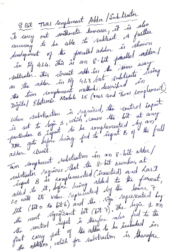
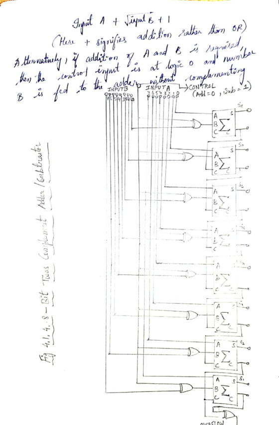
Please Can someone paraphrase this ? : 1.4 Binary Subtractor The subtraction of unsigned binary numbers...
Please Can someone paraphrase this ? : 1.4 Binary Subtractor The subtraction of unsigned binary numbers can be done most conveniently by means of complement. Subtraction A–B can be done by tacking the 2’s complement of B and adding it to A. The 2’s complement can be obtained by taking the 1’s complement and adding one to the least significant pair of bits. The 1’s complement can be implemented with the inverters and a one can be added to the...
VHDL structural code please Design an 8-bit add/subtract in Verilog AND VHDL using any of the...
 VHDL structural code please
Design an 8-bit add/subtract in Verilog AND VHDL using any of the coding styles and language features covered so far in modules 8 and 9. When AS Sel0 it performs an addition, else when AS Sel 1 it performs a subtraction. OpA and OpB are assumed to be signed, 2's-Complement numbers. Hint: Bit-wise XOR AS Sel with OpB before adding it to OpA- see lecture notes Op87.0Add/ Subtract Vout
VHDL structural code please
Design an 8-bit add/subtract in Verilog AND VHDL using any of the coding styles and language features covered so far in modules 8 and 9. When AS Sel0 it performs an addition, else when AS Sel 1 it performs a subtraction. OpA and OpB are assumed to be signed, 2's-Complement numbers. Hint: Bit-wise XOR AS Sel with OpB before adding it to OpA- see lecture notes Op87.0Add/ Subtract Vout
Write an Verilog code for a 8-bit subtractor (Bits are in 1's complement) using the following:...
Write an Verilog code for a 8-bit subtractor (Bits are in 1's complement) using the following: 1. 5-bit parallel adder 2. 3-bit parallel adder The condition are as follows: 1. The Most Significant bits of the subtractor must be given to the 5-bit parallel adder. 2, The Least Significant bits of the subtractor must be given to the 3-bit parallel adder. 3. The input A will be assign to the switches with the least significant bit A[0] linked to SW0....
Implement the 8-bit Gate level ALU shown in the figure below in VHDL (Full adder & subtractor & all logical oper...
 Implement the 8-bit Gate level ALU shown in the figure below in
VHDL (Full adder & subtractor & all logical operations
& flags implementations)
31 ALUControlo Sum31 ALUContro out Sum 10 0 00 ALUControl 、ノ Resullgi Negative Zero Result ALUFlags o Verflow Figure 1 N-bit ALU with output flags
31 ALUControlo Sum31 ALUContro out Sum 10 0 00 ALUControl 、ノ Resullgi Negative Zero Result ALUFlags o Verflow Figure 1 N-bit ALU with output flags
Implement the 8-bit Gate level ALU shown in the figure below in
VHDL (Full adder & subtractor & all logical operations
& flags implementations)
31 ALUControlo Sum31 ALUContro out Sum 10 0 00 ALUControl 、ノ Resullgi Negative Zero Result ALUFlags o Verflow Figure 1 N-bit ALU with output flags
31 ALUControlo Sum31 ALUContro out Sum 10 0 00 ALUControl 、ノ Resullgi Negative Zero Result ALUFlags o Verflow Figure 1 N-bit ALU with output flags
Vhdl language PROJECT REQUIREMENT Design 8*8 bit signed multiplier A*B circuit using Booth Multiplier (you will...
 Vhdl language
PROJECT REQUIREMENT Design 8*8 bit signed multiplier A*B circuit using Booth Multiplier (you will learn about this in the course). . A and B are 8-bits signed numbers. . The operands A and B must be written into registers RA and RB on the negative edge of the LOAD flag. Output of the multiplier is a 16 bit register Z . The project must be written in structural VHDL mode, Each component Implementation and simulation details should be...
Vhdl language
PROJECT REQUIREMENT Design 8*8 bit signed multiplier A*B circuit using Booth Multiplier (you will learn about this in the course). . A and B are 8-bits signed numbers. . The operands A and B must be written into registers RA and RB on the negative edge of the LOAD flag. Output of the multiplier is a 16 bit register Z . The project must be written in structural VHDL mode, Each component Implementation and simulation details should be...
 4. Design a 4-bit Adder / Subtractor. Follow the steps given below. (a) Write the VHDL code for a 1-bit Full Adder. The VHDL code must include an entity and an architecture. (b) Draw the circuit diagram for a 4-bit Adder / Subtractor. The circuit diagram may include the following logic elements: 1-bit Full Adders (shown as a block with inputs and outputs) Any 2-input logic gates Multiplexers Do not draw the logic circuit for the 1-bit Full Adder.
 Construct the 8-bit ripple-carry adder/subtractor for signed integers. Negative numbers are in the 2's complement form. The circuit has inputs X(7:0), Y(7:0), CO, M and outputs S(7:0), carry-out of MSB C8, OFL (OFL 1 when it occurs). The circuit should perform addition and subtraction of 8-bit signed numbers 2. with M-1 and M-0, respectively. a) Obtain the schematic for the 8-bit adder/subtractor with two 4-bit adder/subtractors from problem 1 as building blocks. X, Y, A, B, S can be shown...
 Implement the following bit sequential Adder-Subtractor design. X and Y are two operand inputs and Z is for the control signal i.e. Z is the selection bit. When Z has value 0, the circuit is an adder, meanwhile, the D flip-flop should be initialized to 0 for each addition. When Z has value 1, it performs subtraction, meanwhile, the D flip-flop should be initialized to 1 for each subtraction. Test your Adder-Subtractor circuit on the following operations and use the...
 Using single bit Full Adder (FA) blocks (as shown below) and
required gates, construct a 6-bit Adder/Subtractor for signed
numbers.
Use the signed two’s complement system for the signed
numbers.
Verify your design for the following addition and subtraction by
specifying A as A5A4A3A2A1A0 and B as B5B6B3B2B1B0, determining the
inputs to the FAs and their outputs and showing that the outputs
correspond to the correct results:
a) A-B with A = -13, B = +20 (5 points)
b) A+B...
Using single bit Full Adder (FA) blocks (as shown below) and
required gates, construct a 6-bit Adder/Subtractor for signed
numbers.
Use the signed two’s complement system for the signed
numbers.
Verify your design for the following addition and subtraction by
specifying A as A5A4A3A2A1A0 and B as B5B6B3B2B1B0, determining the
inputs to the FAs and their outputs and showing that the outputs
correspond to the correct results:
a) A-B with A = -13, B = +20 (5 points)
b) A+B...
 (32 pts) Adder/ Subtractor 11. (8 pts) Given a l-bit full adder (you can use the box representation as below) show the circuitry required to make it into a 4-bit full adder and subtractor. 12. (12 pts) Show the hardware required to compute the 4 primary flags for your 4-bit add sub unit carry (C), zero (Z), overflow (V), and sign (N). 13.(12 pts) Show the results for the addition below. Also show the equivalent decimal numbers for each Ain...
 VHDL structural code please
Design an 8-bit add/subtract in Verilog AND VHDL using any of the coding styles and language features covered so far in modules 8 and 9. When AS Sel0 it performs an addition, else when AS Sel 1 it performs a subtraction. OpA and OpB are assumed to be signed, 2's-Complement numbers. Hint: Bit-wise XOR AS Sel with OpB before adding it to OpA- see lecture notes Op87.0Add/ Subtract Vout
VHDL structural code please
Design an 8-bit add/subtract in Verilog AND VHDL using any of the coding styles and language features covered so far in modules 8 and 9. When AS Sel0 it performs an addition, else when AS Sel 1 it performs a subtraction. OpA and OpB are assumed to be signed, 2's-Complement numbers. Hint: Bit-wise XOR AS Sel with OpB before adding it to OpA- see lecture notes Op87.0Add/ Subtract Vout
 Implement the 8-bit Gate level ALU shown in the figure below in
VHDL (Full adder & subtractor & all logical operations
& flags implementations)
31 ALUControlo Sum31 ALUContro out Sum 10 0 00 ALUControl 、ノ Resullgi Negative Zero Result ALUFlags o Verflow Figure 1 N-bit ALU with output flags
31 ALUControlo Sum31 ALUContro out Sum 10 0 00 ALUControl 、ノ Resullgi Negative Zero Result ALUFlags o Verflow Figure 1 N-bit ALU with output flags
Implement the 8-bit Gate level ALU shown in the figure below in
VHDL (Full adder & subtractor & all logical operations
& flags implementations)
31 ALUControlo Sum31 ALUContro out Sum 10 0 00 ALUControl 、ノ Resullgi Negative Zero Result ALUFlags o Verflow Figure 1 N-bit ALU with output flags
31 ALUControlo Sum31 ALUContro out Sum 10 0 00 ALUControl 、ノ Resullgi Negative Zero Result ALUFlags o Verflow Figure 1 N-bit ALU with output flags
 Vhdl language
PROJECT REQUIREMENT Design 8*8 bit signed multiplier A*B circuit using Booth Multiplier (you will learn about this in the course). . A and B are 8-bits signed numbers. . The operands A and B must be written into registers RA and RB on the negative edge of the LOAD flag. Output of the multiplier is a 16 bit register Z . The project must be written in structural VHDL mode, Each component Implementation and simulation details should be...
Vhdl language
PROJECT REQUIREMENT Design 8*8 bit signed multiplier A*B circuit using Booth Multiplier (you will learn about this in the course). . A and B are 8-bits signed numbers. . The operands A and B must be written into registers RA and RB on the negative edge of the LOAD flag. Output of the multiplier is a 16 bit register Z . The project must be written in structural VHDL mode, Each component Implementation and simulation details should be...
Most questions answered within 3 hours.
-
1. An object weighing 40 N rests on a surface. The coefficient
of friction is 0.35....
asked 1 hour ago -
Investor company owns 35% of investee company voting stock and
accounts for the investment under the...
asked 2 hours ago -
The number of major faults on a randomly chosen 1 km stretch of
highway has a...
asked 2 hours ago -
Consider the competitive environment of Starbuck's, Progressive
Insurance, a manufacturing firm with low turnover, or a...
asked 3 hours ago -
3. Gains from trade
Consider two neighbouring island countries called Euphoria and
Contente. They each have...
asked 5 hours ago -
A business executive has the option to invest money in two
plans: Plan A guarantees that...
asked 7 hours ago -
Hello, can someone please help me answer this question?
How much heat is absorbed by a...
asked 7 hours ago -
. A marketing researcher conducted a survey of 25 shoppers
randomly selected at the local mall...
asked 7 hours ago -
Create an comprehensive response to the
following:
Antimicrobial agents work on a multitude of microbes (bacteria,...
asked 7 hours ago -
6.13 LAB: Step counter. Section 6.3.
A pedometer treats walking 2,000 steps as walking 1 mile....
asked 7 hours ago -
(14.2) A block of mass m = 10 kg riding on a frictionless
horizontal plane is...
asked 7 hours ago -
Use any search engine to search for articles about Starbucks
partnership with Tata Companies in India...
asked 7 hours ago