

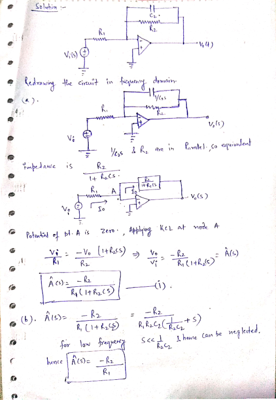
1. Consider the circuit shown below. (a) Derive an expression for thetransfer tion, λ(,)-E(s)R(,). 00pts) (b) Using the transfer function found purt (a), derive an expression for the low- frequeney gain, Aran (5 pts) (c) Using circuit analysis, derive an expression for the low-frequency gain a, A (d) Using the transfer function found in part (al derive an expression for the high- (e) Using circuit analysis, derive an expression for the high-frequency gain, AMP (3 pts) frequency gain, A 5 pts) (5 pes) (0 Express A, (s) in the following fiom Find an expeession for Aa and(10ps) For part。g) through part (I) assanetha R.-IM. R-10kS2. and C,-10nF. (g) Calculate a value for f (5 pes) (h) Calculate a value for λ(r) iff-0. (5pts) () Repeat Part (h) iff 100 Hz. (Sps) G) Repeat Part (h)- kHz. (Spes) ) Repeat Pant (h) it f-(5 pts (I) Repeat Part (h)if-10 kHz (5 pts)
Homework Answers


Add Answer to:
L Consider the circuit shown below by Using the traar fanction found in pat (ak derive an cxpress...
Problem 1 (25 Pts) Consider the OP amp circuit shown below with R = 100kN and...
 Problem 1 (25 Pts) Consider the OP amp circuit shown below with R = 100kN and C = 1(10)-5 F: for the circuit in terms of frequency f(Hz). VO Part b) 5 pts Compute the gain of at as a function of frequency f(Hz). Vi Part c) 10 pts Compute the corresponding gains at 100, 1000, 10000 Hz. Part a) 10 pts Find the complex transfer function in R 3R 5R Via V.
Problem 1 (25 Pts) Consider the OP amp circuit shown below with R = 100kN and...
 Problem 1 (25 Pts) Consider the OP amp circuit shown below with R = 100kN and C = 1(10)-5 F: Part a) 10 pts Find the complex transfer function for the circuit in terms of frequency f (Hz). Vi Part b) 5 pts Compute the gain of at as a function of frequency f(Hz). Part c) 10 pts Compute the corresponding gains at 100, 1000, 10000 Hz. Vo R 3R 5R с Vů V.
2. Consider the parallel RLC circuit mentioned in class, with C = 1, L = 4, and R = 1 (a) Derive the iin-to v transfer...
 2. Consider the parallel RLC circuit mentioned in class, with C = 1, L = 4, and R = 1 (a) Derive the iin-to v transfer function, i.e., the circuit's impedance (b) Compute and plot the step response (c) Plot the magnitude of the frequency response function, G(jw) as a function of Compute, via analysis, the frequency wmar Wwhere maximum gain |G(jw)| is w. maximized (d) Verify your results using MATLAB: Plot the system's response to a step, and to...
1- Design a lossy integrator op-amp circuit using op-amp 741. First, derive an expression for - V...
 UPLOAD PSPICE SIMULATION TO VERIFY CALCULATIONS
1- Design a lossy integrator op-amp circuit using op-amp 741. First, derive an expression for - Vo Then assign values to circuit components in order to have Gai 1. Verify your design with a PSpice simulation. Since gain value depends on Vi frequency, perform an AC sweep analysis (frequency response) to obtain which frequency gives you this gain. Report this trequency. IVil
1- Design a lossy integrator op-amp circuit using op-amp 741. First, derive...
UPLOAD PSPICE SIMULATION TO VERIFY CALCULATIONS
1- Design a lossy integrator op-amp circuit using op-amp 741. First, derive an expression for - Vo Then assign values to circuit components in order to have Gai 1. Verify your design with a PSpice simulation. Since gain value depends on Vi frequency, perform an AC sweep analysis (frequency response) to obtain which frequency gives you this gain. Report this trequency. IVil
1- Design a lossy integrator op-amp circuit using op-amp 741. First, derive...
Problem 1 (25 Pts) Consider the OP amp circuit shown below with R = 100kN and...
 Problem 1 (25 Pts) Consider the OP amp circuit shown below with R = 100kN and C = 1(10)-5F: Part a) 10 pts Find the complex transfer functions for the circuit in terms of frequency f (Hz). Part b) 5 pts Compute the gain of Wat as a function of frequency f (Hz). Part e) 10 pts Compute the corresponding gains at 100, 1000, 10000 Hz. R 3R 5R с Vi ve
Problem 1 (25 Pts) Consider the OP amp circuit shown below with R = 100kN and...
 Problem 1 (25 Pts) Consider the OP amp circuit shown below with R = 100kN and C = 1(10)-5F: Part a) 10 pts Find the complex transfer functions for the circuit in terms of frequency f(Hz). Part b) 5 pts Compute the gain ofat as a function of frequency f(Hz). Parte) 10 pts Compute the corresponding gains at 100, 1000, 10000 Hz. R 3R 5R Vi ve
Problem 1 (25 Pts) Consider the OP amp circuit shown below with R = 100kN and...
 Problem 1 (25 Pts) Consider the OP amp circuit shown below with R = 100kN and C = 1(10)-SP: Part a) 10 pts Find the complex transfer function for the circuit in terms of frequency f(Hz). Part b) 5 pts Compute the gain ofat as a function of frequency f(Hz). Parte) 10 pts Compute the corresponding gains at 100, 1000, 10000 Hz. R 3R 5R Vim -VO
Experimental methodology Problem 1 (25 Pts) Consider the OP amp circuit shown below with R =...
 Experimental methodology
Problem 1 (25 Pts) Consider the OP amp circuit shown below with R = 100kN and C = 1(10)-SP: Part a) 10 pts Find the complex transfer functions for the circuit in terms of frequency f (Hz). Part b) 5 pts Compute the gain of sat as a function of frequency f (Hz). Part e) 10 pts Compute the corresponding gains at 100, 1000, 10000 Hz. R 3R 5R protein Vi - Vo
Experimental methodology
Problem 1 (25 Pts) Consider the OP amp circuit shown below with R = 100kN and C = 1(10)-SP: Part a) 10 pts Find the complex transfer functions for the circuit in terms of frequency f (Hz). Part b) 5 pts Compute the gain of sat as a function of frequency f (Hz). Part e) 10 pts Compute the corresponding gains at 100, 1000, 10000 Hz. R 3R 5R protein Vi - Vo
VO Problem 1 (25 Pts) Consider the OP amp circuit shown below with R = 100k12...
 VO Problem 1 (25 Pts) Consider the OP amp circuit shown below with R = 100k12 and C = 1(10)-5 F: Part a) 10 pts Find the complex transfer function for the circuit in terms of frequency f (Hz). Vi Part b) 5 pts Compute the gain of ko at as a function of frequency f (Hz). Part c) 10 pts Compute the corresponding gains at 100, 1000, 10000 Hz. Vi R BR 5R с Vi - Ve
Problem 1 (25 Pts) Consider the OP amp circuit shown below with R = 100kN and...
 Problem 1 (25 Pts) Consider the OP amp circuit shown below with R = 100kN and C = 1(10): Parta) 10 pts Find the complex transfer function for the circuit in terms of frequency f(Hz). Part b) 5 pts Compute the gain of at as a function of frequency f(Hz). Parte) 10 pts Compute the corresponding gains at 100, 1000, 10000 Hz. R 3R 5R Vå w V
 Problem 1 (25 Pts) Consider the OP amp circuit shown below with R = 100kN and C = 1(10)-5 F: for the circuit in terms of frequency f(Hz). VO Part b) 5 pts Compute the gain of at as a function of frequency f(Hz). Vi Part c) 10 pts Compute the corresponding gains at 100, 1000, 10000 Hz. Part a) 10 pts Find the complex transfer function in R 3R 5R Via V.
 Problem 1 (25 Pts) Consider the OP amp circuit shown below with R = 100kN and C = 1(10)-5 F: Part a) 10 pts Find the complex transfer function for the circuit in terms of frequency f (Hz). Vi Part b) 5 pts Compute the gain of at as a function of frequency f(Hz). Part c) 10 pts Compute the corresponding gains at 100, 1000, 10000 Hz. Vo R 3R 5R с Vů V.
 2. Consider the parallel RLC circuit mentioned in class, with C = 1, L = 4, and R = 1 (a) Derive the iin-to v transfer function, i.e., the circuit's impedance (b) Compute and plot the step response (c) Plot the magnitude of the frequency response function, G(jw) as a function of Compute, via analysis, the frequency wmar Wwhere maximum gain |G(jw)| is w. maximized (d) Verify your results using MATLAB: Plot the system's response to a step, and to...
 UPLOAD PSPICE SIMULATION TO VERIFY CALCULATIONS
1- Design a lossy integrator op-amp circuit using op-amp 741. First, derive an expression for - Vo Then assign values to circuit components in order to have Gai 1. Verify your design with a PSpice simulation. Since gain value depends on Vi frequency, perform an AC sweep analysis (frequency response) to obtain which frequency gives you this gain. Report this trequency. IVil
1- Design a lossy integrator op-amp circuit using op-amp 741. First, derive...
UPLOAD PSPICE SIMULATION TO VERIFY CALCULATIONS
1- Design a lossy integrator op-amp circuit using op-amp 741. First, derive an expression for - Vo Then assign values to circuit components in order to have Gai 1. Verify your design with a PSpice simulation. Since gain value depends on Vi frequency, perform an AC sweep analysis (frequency response) to obtain which frequency gives you this gain. Report this trequency. IVil
1- Design a lossy integrator op-amp circuit using op-amp 741. First, derive...
 Problem 1 (25 Pts) Consider the OP amp circuit shown below with R = 100kN and C = 1(10)-5F: Part a) 10 pts Find the complex transfer functions for the circuit in terms of frequency f (Hz). Part b) 5 pts Compute the gain of Wat as a function of frequency f (Hz). Part e) 10 pts Compute the corresponding gains at 100, 1000, 10000 Hz. R 3R 5R с Vi ve
 Problem 1 (25 Pts) Consider the OP amp circuit shown below with R = 100kN and C = 1(10)-5F: Part a) 10 pts Find the complex transfer functions for the circuit in terms of frequency f(Hz). Part b) 5 pts Compute the gain ofat as a function of frequency f(Hz). Parte) 10 pts Compute the corresponding gains at 100, 1000, 10000 Hz. R 3R 5R Vi ve
 Problem 1 (25 Pts) Consider the OP amp circuit shown below with R = 100kN and C = 1(10)-SP: Part a) 10 pts Find the complex transfer function for the circuit in terms of frequency f(Hz). Part b) 5 pts Compute the gain ofat as a function of frequency f(Hz). Parte) 10 pts Compute the corresponding gains at 100, 1000, 10000 Hz. R 3R 5R Vim -VO
 Experimental methodology
Problem 1 (25 Pts) Consider the OP amp circuit shown below with R = 100kN and C = 1(10)-SP: Part a) 10 pts Find the complex transfer functions for the circuit in terms of frequency f (Hz). Part b) 5 pts Compute the gain of sat as a function of frequency f (Hz). Part e) 10 pts Compute the corresponding gains at 100, 1000, 10000 Hz. R 3R 5R protein Vi - Vo
Experimental methodology
Problem 1 (25 Pts) Consider the OP amp circuit shown below with R = 100kN and C = 1(10)-SP: Part a) 10 pts Find the complex transfer functions for the circuit in terms of frequency f (Hz). Part b) 5 pts Compute the gain of sat as a function of frequency f (Hz). Part e) 10 pts Compute the corresponding gains at 100, 1000, 10000 Hz. R 3R 5R protein Vi - Vo
 VO Problem 1 (25 Pts) Consider the OP amp circuit shown below with R = 100k12 and C = 1(10)-5 F: Part a) 10 pts Find the complex transfer function for the circuit in terms of frequency f (Hz). Vi Part b) 5 pts Compute the gain of ko at as a function of frequency f (Hz). Part c) 10 pts Compute the corresponding gains at 100, 1000, 10000 Hz. Vi R BR 5R с Vi - Ve
 Problem 1 (25 Pts) Consider the OP amp circuit shown below with R = 100kN and C = 1(10): Parta) 10 pts Find the complex transfer function for the circuit in terms of frequency f(Hz). Part b) 5 pts Compute the gain of at as a function of frequency f(Hz). Parte) 10 pts Compute the corresponding gains at 100, 1000, 10000 Hz. R 3R 5R Vå w V
Most questions answered within 3 hours.
-
what are the differences between these?
a. shear force.
b. shear stress.
c. Bending Moment.
d....
asked 6 minutes ago -
The proportion of adult women in a certain geographical region
is approximately 51%. A marketing survey...
asked 14 minutes ago -
I am trying to answer a question that is asking why there was no
evidence of...
asked 24 minutes ago -
Power elecrtonics: buck converter?
Calculate and plot (via excel/MATLAB) the average V(out) of a
buck converter...
asked 26 minutes ago -
PLEASE USE PYTHON
training error should strictly decrease as the degree of the
hypothesis polynomials increases....
asked 30 minutes ago -
Using the Table and data below, create a procedure that accepts
product ID as a parameter...
asked 32 minutes ago -
Suppose X follows an exponential distribution with mean 7.5.
Determine the conditional probability P(x > 2.5...
asked 55 minutes ago -
Young softball batters are often instructed to “choke-up on the
bat” by their coach. In terms...
asked 58 minutes ago -
Suppose that you are an official with Mexico's economic
development agency. Write a one-page memo detailing...
asked 1 hour ago -
If you were an international firm, why would you support the
concept of global free trade?...
asked 1 hour ago -
Cisco packet tracer
Q1) Do you get any changes of IP address when packet is
traversing...
asked 2 hours ago -
What is the pressure inside a 33.0 L container holding 106.4 kg
of argon gas at...
asked 3 hours ago