
Homework Answers
Given that
we have to Design a PI controller whose compensator zero located at -0.1


Add Answer to:
Design a PI controller to drive the step-response error to zero for the negative unity feedback s...
Problem 6 Design a PI controller to drive the step-response error to zero for the negative unity ...
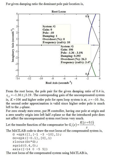
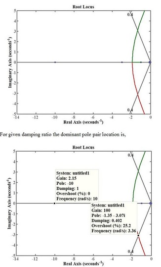
 Problem 6 Design a PI controller to drive the step-response error to zero for the negative unity feedback system shown in Fig. 1, where G(s) = (s+1)(s + 3)(s+ io). The system operates with a damping factor of 0.4 Design a PI controller whose compensator zero located at-0.1 Use MATLAB or any other computer program to simulate the step response to closed-loop system
Problem 6 Design a PI controller to drive the step-response error to zero for the negative unity...
Problem 6 Design a PI controller to drive the step-response error to zero for the negative unity feedback system shown in Fig. 1, where G(s) = (s+1)(s + 3)(s+ io). The system operates with a damping factor of 0.4 Design a PI controller whose compensator zero located at-0.1 Use MATLAB or any other computer program to simulate the step response to closed-loop system
Problem 6 Design a PI controller to drive the step-response error to zero for the negative unity...
Design a PI controller to drive the step response error to zero for the unity feedback...
 Design a PI controller to drive the step response error to zero for the unity feedback system shown in Figure P9.1, where G(s) s1) (s +3) (s 10) The system operates with a damping ratio of 0.5. Compare the specifications of the uncompensated and compensated systems. [Section: 9.2] C(s) FIGURE P9.1
Consider a unity-feedback control system with a PI controller Gpr(s) and a plant G(s) in cascade. In particular, the plant transfer function is given as 2. G(s) = s+4, and the PI controller trans...
 Consider a unity-feedback control system with a PI controller Gpr(s) and a plant G(s) in cascade. In particular, the plant transfer function is given as 2. G(s) = s+4, and the PI controller transfer function is of the forrm KI p and Ki are the proportional and integral controller gains, respectively where K Design numerical values for Kp and Ki such that the closed-loop control system has a step- response settling time T, 0.5 seconds with a damping ratio of...
1. A system with unity feedback is shown below. The feed-forward transfer function is G(s). Sketch...
 1. A system with unity feedback is shown below. The feed-forward transfer function is G(s). Sketch the root locus for the variations in the values of pi. R(9)+ 66) 69? Fig. 1: Unity-feedback closed-loop system G(s)= 100 s(s+ p) 2. The following closed-loop systems in Fig. 2 and Fig. 3 are operating with a damping ratio of 0.866 (S =0.866). The system in Fig. 2 doesn't have a PI controller, while the one in Fig. 3 does. Gain Plant R(S)...
Compensator Plant 100 R(s) sta Y(s) For the unity feedback system shown in Fig. 3.55, specify t...
 Compensator Plant 100 R(s) sta Y(s) For the unity feedback system shown in Fig. 3.55, specify the gain and pole location of the compensator so that the overall closed-loop response to a unit- step input has an overshoot of no more than 30%, and a 2% settling time of no more than 0.2 sec. Verify your design using Matlab. 3.27
Compensator Plant 100 R(s) sta Y(s)
For the unity feedback system shown in Fig. 3.55, specify the gain and pole...
Compensator Plant 100 R(s) sta Y(s) For the unity feedback system shown in Fig. 3.55, specify the gain and pole location of the compensator so that the overall closed-loop response to a unit- step input has an overshoot of no more than 30%, and a 2% settling time of no more than 0.2 sec. Verify your design using Matlab. 3.27
Compensator Plant 100 R(s) sta Y(s)
For the unity feedback system shown in Fig. 3.55, specify the gain and pole...
A uncompensated (un-controlled) feedback system with and plant transfer function are shown below. Design a PI...
 A uncompensated (un-controlled) feedback system with and plant
transfer function are shown below. Design a PI controller that you
could add that will drive the steady-state error to zero for a
unity step reference, and operate with a damping ratio of 0.5.
Provide the resulting %OS, and 2% settling time. You must show the
analytical process and all steps you took to design your
controller.
Use MATLAB/Simulink to simulate the system and your feed-back
controller for a unity step input...
A uncompensated (un-controlled) feedback system with and plant
transfer function are shown below. Design a PI controller that you
could add that will drive the steady-state error to zero for a
unity step reference, and operate with a damping ratio of 0.5.
Provide the resulting %OS, and 2% settling time. You must show the
analytical process and all steps you took to design your
controller.
Use MATLAB/Simulink to simulate the system and your feed-back
controller for a unity step input...
17. Consider unity feedback system with uncompensated forward transfer function a given by: K G(s) s+3)(s 6) The system...
 17. Consider unity feedback system with uncompensated forward transfer function a given by: K G(s) s+3)(s 6) The system requires a damping ratio of 0.5. If the design point is at -1.54 j2.66, design a PI controller to drive the steady-state error of the response to zero
17. Consider unity feedback system with uncompensated forward transfer function a given by: K G(s) s+3)(s 6) The system requires a damping ratio of 0.5. If the design point is at -1.54 j2.66,...
17. Consider unity feedback system with uncompensated forward transfer function a given by: K G(s) s+3)(s 6) The system requires a damping ratio of 0.5. If the design point is at -1.54 j2.66, design a PI controller to drive the steady-state error of the response to zero
17. Consider unity feedback system with uncompensated forward transfer function a given by: K G(s) s+3)(s 6) The system requires a damping ratio of 0.5. If the design point is at -1.54 j2.66,...
Problem 2: Given the plant G,le)+2( +3) design a PI compensator Gc(s)-K Ш such the closed-loop...
 Problem 2: Given the plant G,le)+2( +3) design a PI compensator Gc(s)-K Ш such the closed-loop unity feedback system has two dominant poles at s1.2 =-1 ±j. Using Matlab ritool (or simulink), simulate your closed loop system to show that the unit-step response of the system has PO ~ 4.3%, tr 2.35 sec, and 4 ะ 4.15 sec. Compute the closed-loop poles and zeros.
PD & PID controller design Consider a unity feedback system with open loop transfer function, G(s)...
 PD & PID controller design Consider a unity feedback system with open loop transfer function, G(s) = 20/s(s+2)(8+4). Design a PD controller so that the closed loop has a damping ratio of 0.8 and natural frequency of oscillation as 2 rad/sec. b) 100 Consider a unity feedback system with open loop transfer function, aus. Design a PID controller, so that the phase margin of (S-1) (s + 2) (s+10) the system is 45° at a frequency of 4 rad/scc and...
1. Consider a unity feedback control system with the transfer function G(s) = 1/[s(s+ 2)] in...
1. Consider a unity feedback control system with the transfer function G(s) = 1/[s(s+ 2)] in the forward path. (a) Design a proportional controller that yields a stable system with percent overshoot less that 5% for the step input (b) Find settling time and peak time of the closed-loop system designed in part (a); (c) Design a PD compensator that reduces the settling time computed in (b) by a factor of 4 while keeping the percent overshoot less that 5%...
 Problem 6 Design a PI controller to drive the step-response error to zero for the negative unity feedback system shown in Fig. 1, where G(s) = (s+1)(s + 3)(s+ io). The system operates with a damping factor of 0.4 Design a PI controller whose compensator zero located at-0.1 Use MATLAB or any other computer program to simulate the step response to closed-loop system
Problem 6 Design a PI controller to drive the step-response error to zero for the negative unity...
Problem 6 Design a PI controller to drive the step-response error to zero for the negative unity feedback system shown in Fig. 1, where G(s) = (s+1)(s + 3)(s+ io). The system operates with a damping factor of 0.4 Design a PI controller whose compensator zero located at-0.1 Use MATLAB or any other computer program to simulate the step response to closed-loop system
Problem 6 Design a PI controller to drive the step-response error to zero for the negative unity...
 Design a PI controller to drive the step response error to zero for the unity feedback system shown in Figure P9.1, where G(s) s1) (s +3) (s 10) The system operates with a damping ratio of 0.5. Compare the specifications of the uncompensated and compensated systems. [Section: 9.2] C(s) FIGURE P9.1
 Consider a unity-feedback control system with a PI controller Gpr(s) and a plant G(s) in cascade. In particular, the plant transfer function is given as 2. G(s) = s+4, and the PI controller transfer function is of the forrm KI p and Ki are the proportional and integral controller gains, respectively where K Design numerical values for Kp and Ki such that the closed-loop control system has a step- response settling time T, 0.5 seconds with a damping ratio of...
 1. A system with unity feedback is shown below. The feed-forward transfer function is G(s). Sketch the root locus for the variations in the values of pi. R(9)+ 66) 69? Fig. 1: Unity-feedback closed-loop system G(s)= 100 s(s+ p) 2. The following closed-loop systems in Fig. 2 and Fig. 3 are operating with a damping ratio of 0.866 (S =0.866). The system in Fig. 2 doesn't have a PI controller, while the one in Fig. 3 does. Gain Plant R(S)...
 Compensator Plant 100 R(s) sta Y(s) For the unity feedback system shown in Fig. 3.55, specify the gain and pole location of the compensator so that the overall closed-loop response to a unit- step input has an overshoot of no more than 30%, and a 2% settling time of no more than 0.2 sec. Verify your design using Matlab. 3.27
Compensator Plant 100 R(s) sta Y(s)
For the unity feedback system shown in Fig. 3.55, specify the gain and pole...
Compensator Plant 100 R(s) sta Y(s) For the unity feedback system shown in Fig. 3.55, specify the gain and pole location of the compensator so that the overall closed-loop response to a unit- step input has an overshoot of no more than 30%, and a 2% settling time of no more than 0.2 sec. Verify your design using Matlab. 3.27
Compensator Plant 100 R(s) sta Y(s)
For the unity feedback system shown in Fig. 3.55, specify the gain and pole...
 A uncompensated (un-controlled) feedback system with and plant
transfer function are shown below. Design a PI controller that you
could add that will drive the steady-state error to zero for a
unity step reference, and operate with a damping ratio of 0.5.
Provide the resulting %OS, and 2% settling time. You must show the
analytical process and all steps you took to design your
controller.
Use MATLAB/Simulink to simulate the system and your feed-back
controller for a unity step input...
A uncompensated (un-controlled) feedback system with and plant
transfer function are shown below. Design a PI controller that you
could add that will drive the steady-state error to zero for a
unity step reference, and operate with a damping ratio of 0.5.
Provide the resulting %OS, and 2% settling time. You must show the
analytical process and all steps you took to design your
controller.
Use MATLAB/Simulink to simulate the system and your feed-back
controller for a unity step input...
 17. Consider unity feedback system with uncompensated forward transfer function a given by: K G(s) s+3)(s 6) The system requires a damping ratio of 0.5. If the design point is at -1.54 j2.66, design a PI controller to drive the steady-state error of the response to zero
17. Consider unity feedback system with uncompensated forward transfer function a given by: K G(s) s+3)(s 6) The system requires a damping ratio of 0.5. If the design point is at -1.54 j2.66,...
17. Consider unity feedback system with uncompensated forward transfer function a given by: K G(s) s+3)(s 6) The system requires a damping ratio of 0.5. If the design point is at -1.54 j2.66, design a PI controller to drive the steady-state error of the response to zero
17. Consider unity feedback system with uncompensated forward transfer function a given by: K G(s) s+3)(s 6) The system requires a damping ratio of 0.5. If the design point is at -1.54 j2.66,...
 Problem 2: Given the plant G,le)+2( +3) design a PI compensator Gc(s)-K Ш such the closed-loop unity feedback system has two dominant poles at s1.2 =-1 ±j. Using Matlab ritool (or simulink), simulate your closed loop system to show that the unit-step response of the system has PO ~ 4.3%, tr 2.35 sec, and 4 ะ 4.15 sec. Compute the closed-loop poles and zeros.
 PD & PID controller design Consider a unity feedback system with open loop transfer function, G(s) = 20/s(s+2)(8+4). Design a PD controller so that the closed loop has a damping ratio of 0.8 and natural frequency of oscillation as 2 rad/sec. b) 100 Consider a unity feedback system with open loop transfer function, aus. Design a PID controller, so that the phase margin of (S-1) (s + 2) (s+10) the system is 45° at a frequency of 4 rad/scc and...
Most questions answered within 3 hours.
-
A 6.5 cm diameter ball has a terminal speed of 22 m/s. What is
the ball's...
asked 6 minutes ago -
Name two areas of the human body with the highest concentration
of lymph nodes and speculate...
asked 10 minutes ago -
Angel Corporation has $10,000,000 of
8.0% 25 year bonds dated May 1, 2018 with interest payable...
asked 45 minutes ago -
7.
________ involves individuals trading goods they already have or
providing services in exchange for something...
asked 49 minutes ago -
Share your research problem. What databases did you search as
you gathered evidence to support your...
asked 49 minutes ago -
what process occurs to form microspores and megaspores in flowering
plants?
asked 56 minutes ago -
C++
I need to use the function getData to put in all my data using
arrays....
asked 56 minutes ago -
A block is hung by a string from the inside roof of a van. When
the...
asked 1 hour ago -
Do you think companies should not go for long term debt in their
capital structure to...
asked 1 hour ago -
I create an address book where the user enters the name, phone
and email in the...
asked 1 hour ago -
The production capacity for acrylonitrile
(C3H3N) in the United States exceeds 2
million pounds per year....
asked 1 hour ago -
explain and comment out your answer
43. How many address lines are required to address a...
asked 1 hour ago