
RLC
Homework Answers

Add Answer to:
The loose leaf paper was just my initial guess and brain storm. looking for how to do it
The final answer is on the bottom of the loose leaf, i just dont know how to get to it. Vo= -35.2...
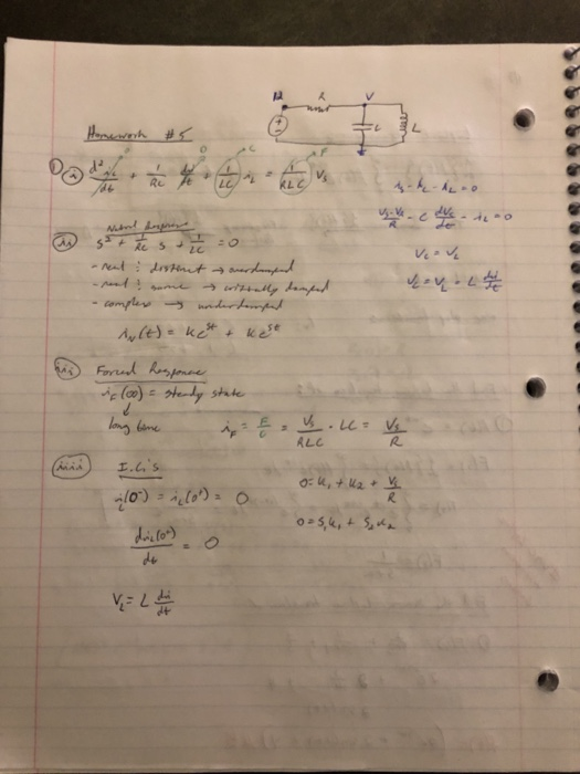
 the final answer is on the bottom of the loose leaf, i just
dont know how to get to it.
Vo= -35.2e^(-3200t) + 11.2e^(-800t) + 20
t _> 0
5. The switch in the circuit has been in position "a" for a long time. At t = 0 the switch instantaneously moves to position b. Find Vo(t) for t 20. tro 50nH 781V(t) วา , ゴウr. IEC 겨e 2 0 07쿠 2 っ7 (
5. The switch in the circuit...
the final answer is on the bottom of the loose leaf, i just
dont know how to get to it.
Vo= -35.2e^(-3200t) + 11.2e^(-800t) + 20
t _> 0
5. The switch in the circuit has been in position "a" for a long time. At t = 0 the switch instantaneously moves to position b. Find Vo(t) for t 20. tro 50nH 781V(t) วา , ゴウr. IEC 겨e 2 0 07쿠 2 っ7 (
5. The switch in the circuit...
Assume that the inductor in this circuit is an ideal (lossless) device, initial current is 0A....
 Assume that the inductor in this circuit is an ideal
(lossless) device, initial current is 0A. At t=0, turn on the
switch; at t= 5t, turn off the switch. a-f please
2. Assume that the inductor in this circuit is an ideal (lossless) device, initial current is OA. At t-o, turn on the switch; at t. 5 τ, turn off the switch. (50pts) For 0 s t s5r: switch on a) Find the Thevenin equivalent circuit for the circuit inside...
Assume that the inductor in this circuit is an ideal
(lossless) device, initial current is 0A. At t=0, turn on the
switch; at t= 5t, turn off the switch. a-f please
2. Assume that the inductor in this circuit is an ideal (lossless) device, initial current is OA. At t-o, turn on the switch; at t. 5 τ, turn off the switch. (50pts) For 0 s t s5r: switch on a) Find the Thevenin equivalent circuit for the circuit inside...
Problem 5 (20 points) No energy is stored in the 100 mH inductor or the 0.4...
 Problem 5 (20 points) No energy is stored in the 100 mH inductor or the 0.4 LF capacitor when the switch in the circuit shown in figure below is closed. 0.1 H -O 2800 0.4 F 50 V uc Fig. 5 a) Find the values of a and co b) What is the type of circuit response for t>0? c)What is the initial voltage across the capacitor at t=0- and at t=0+? d) Find an expression for the current through...
When do you include the negative in current divider circuits? In this example In this example...
 When do you include the negative in current divider circuits? In
this example In this example the current is negative and I do not
understand why.
Example 7.1 Determining the Naturasose Example 7.1 Determining the Natural Response of an RL Circuit RL Circuit The switch in the circuit shown in Fig. 7.7 has been closed for a long time before it is opened at -0. Find b) We find the current in the 40? resistor most easily by using current...
When do you include the negative in current divider circuits? In
this example In this example the current is negative and I do not
understand why.
Example 7.1 Determining the Naturasose Example 7.1 Determining the Natural Response of an RL Circuit RL Circuit The switch in the circuit shown in Fig. 7.7 has been closed for a long time before it is opened at -0. Find b) We find the current in the 40? resistor most easily by using current...
MATLAB question. Please answer all the questions and also upload the code by MATLAB. Thanks. Down vote if no code provided. For the circuit shown above, at the moment t = 0, the switch is closed, fin...
 MATLAB question. Please answer all the questions and also upload
the code by MATLAB. Thanks. Down vote if no code provided.
For the circuit shown above, at the moment t = 0, the switch is closed, find w(t) for 120, No energy is stored in the capacitor and inductor at moment t-0 1. Write the dynamic model for RLC circuit after t> 0? a. Show all vour work and calculations b. Write down the characteristic equation of the transfer function...
MATLAB question. Please answer all the questions and also upload
the code by MATLAB. Thanks. Down vote if no code provided.
For the circuit shown above, at the moment t = 0, the switch is closed, find w(t) for 120, No energy is stored in the capacitor and inductor at moment t-0 1. Write the dynamic model for RLC circuit after t> 0? a. Show all vour work and calculations b. Write down the characteristic equation of the transfer function...
Problem 7.10 In the circuit the switch has been closed for a long time before opening...
 Problem 7.10 In the circuit the switch has been closed for a long time before opening at t=0. (Figure 1) Part A Find the value of L so that v. (t) equals 0.5v. (0+) when t= 2 ms. Take R = 11 12 Express your answer with the appropriate units. TH TA ? L = 9 H Submit Previous Answers Request Answer * Incorrect; Try Again; 9 attempts remaining Part B Find the percentage of the stored energy that has...
4) Midterm question Problem 2 (30 points) C=30 uF The air capacitors with C=Cq=3.0 MF, C=2.04F...
 4) Midterm question Problem 2 (30 points) C=30 uF The air capacitors with C=Cq=3.0 MF, C=2.04F and C3= 1.0F are connected to a Vo battery as shown. If the charge on C2 is Q2=20.0 C, | ,2015 Foton C1.0 F (a) (15 pts. Find the equivalent capacitance of the circuit. (b) (15 pts.) Find V. 1) A charge Q is placed on a capacitor of capacitance C=C. The capacitor is then, connected to a resistor and another capacitor of capacitance...
just do question 26 and 30 and show all your work (a) Select R so that 26. For the cincuit of Fig. 943,.40 30u-) m v...
 just do question 26 and 30 and show all your work
(a) Select R so that 26. For the cincuit of Fig. 943,.40 30u-) m v(0+) 6 V. (b) Compute (2 ms). (c) Determine the settling time of the capacitor voltage. (d) Is the inductor current settling time the same as your answer to part (c)? 27. The current source in Fig. 9.43 is id) = 101(1-1) μ A. (a) Select Ri such that iLO")-2 μΑ. Compute L at t-500...
just do question 26 and 30 and show all your work
(a) Select R so that 26. For the cincuit of Fig. 943,.40 30u-) m v(0+) 6 V. (b) Compute (2 ms). (c) Determine the settling time of the capacitor voltage. (d) Is the inductor current settling time the same as your answer to part (c)? 27. The current source in Fig. 9.43 is id) = 101(1-1) μ A. (a) Select Ri such that iLO")-2 μΑ. Compute L at t-500...
You have been asked to design a circuit, shown below, that will deliver a high-current, slightly underdamped, sinusoidal current pulse to a resistive load when the switch is closed at t = 0. You are g...
 You have been asked to design a circuit, shown below, that will
deliver a high-current, slightly
underdamped, sinusoidal current pulse to a resistive load when the
switch is closed at t = 0. You
are given the design requirements and parameters listed in the
table:
a) What values of L and C are required to meet the
specifications?
b) Calculate the time of the first current peak.
c) Calculate the maximum current delivered by the capacitor?
d) Calculate the value...
You have been asked to design a circuit, shown below, that will
deliver a high-current, slightly
underdamped, sinusoidal current pulse to a resistive load when the
switch is closed at t = 0. You
are given the design requirements and parameters listed in the
table:
a) What values of L and C are required to meet the
specifications?
b) Calculate the time of the first current peak.
c) Calculate the maximum current delivered by the capacitor?
d) Calculate the value...
[6] 2. In the previous problem, how long after switch is closed until the magnetic field...
 [6] 2. In the previous problem, how long after switch is closed until the magnetic field is stable? Answer: (a) 1.38 ms. (6) 1.85 ms (c) 2.33 ms. (d) 2.79 ms. (e) 341 ms. (1) - [8] 3. An AC generator is connected to a circuit. The generator's emfis E(0) - 152 V sin(at). If the maximum current that results is 150 mA circuit, -5.01 x 10rad/s and the phase angle is -85.6 degrees, complete the following (0) = sin...
 the final answer is on the bottom of the loose leaf, i just
dont know how to get to it.
Vo= -35.2e^(-3200t) + 11.2e^(-800t) + 20
t _> 0
5. The switch in the circuit has been in position "a" for a long time. At t = 0 the switch instantaneously moves to position b. Find Vo(t) for t 20. tro 50nH 781V(t) วา , ゴウr. IEC 겨e 2 0 07쿠 2 っ7 (
5. The switch in the circuit...
the final answer is on the bottom of the loose leaf, i just
dont know how to get to it.
Vo= -35.2e^(-3200t) + 11.2e^(-800t) + 20
t _> 0
5. The switch in the circuit has been in position "a" for a long time. At t = 0 the switch instantaneously moves to position b. Find Vo(t) for t 20. tro 50nH 781V(t) วา , ゴウr. IEC 겨e 2 0 07쿠 2 っ7 (
5. The switch in the circuit...
 Assume that the inductor in this circuit is an ideal
(lossless) device, initial current is 0A. At t=0, turn on the
switch; at t= 5t, turn off the switch. a-f please
2. Assume that the inductor in this circuit is an ideal (lossless) device, initial current is OA. At t-o, turn on the switch; at t. 5 τ, turn off the switch. (50pts) For 0 s t s5r: switch on a) Find the Thevenin equivalent circuit for the circuit inside...
Assume that the inductor in this circuit is an ideal
(lossless) device, initial current is 0A. At t=0, turn on the
switch; at t= 5t, turn off the switch. a-f please
2. Assume that the inductor in this circuit is an ideal (lossless) device, initial current is OA. At t-o, turn on the switch; at t. 5 τ, turn off the switch. (50pts) For 0 s t s5r: switch on a) Find the Thevenin equivalent circuit for the circuit inside...
 Problem 5 (20 points) No energy is stored in the 100 mH inductor or the 0.4 LF capacitor when the switch in the circuit shown in figure below is closed. 0.1 H -O 2800 0.4 F 50 V uc Fig. 5 a) Find the values of a and co b) What is the type of circuit response for t>0? c)What is the initial voltage across the capacitor at t=0- and at t=0+? d) Find an expression for the current through...
 When do you include the negative in current divider circuits? In
this example In this example the current is negative and I do not
understand why.
Example 7.1 Determining the Naturasose Example 7.1 Determining the Natural Response of an RL Circuit RL Circuit The switch in the circuit shown in Fig. 7.7 has been closed for a long time before it is opened at -0. Find b) We find the current in the 40? resistor most easily by using current...
When do you include the negative in current divider circuits? In
this example In this example the current is negative and I do not
understand why.
Example 7.1 Determining the Naturasose Example 7.1 Determining the Natural Response of an RL Circuit RL Circuit The switch in the circuit shown in Fig. 7.7 has been closed for a long time before it is opened at -0. Find b) We find the current in the 40? resistor most easily by using current...
 MATLAB question. Please answer all the questions and also upload
the code by MATLAB. Thanks. Down vote if no code provided.
For the circuit shown above, at the moment t = 0, the switch is closed, find w(t) for 120, No energy is stored in the capacitor and inductor at moment t-0 1. Write the dynamic model for RLC circuit after t> 0? a. Show all vour work and calculations b. Write down the characteristic equation of the transfer function...
MATLAB question. Please answer all the questions and also upload
the code by MATLAB. Thanks. Down vote if no code provided.
For the circuit shown above, at the moment t = 0, the switch is closed, find w(t) for 120, No energy is stored in the capacitor and inductor at moment t-0 1. Write the dynamic model for RLC circuit after t> 0? a. Show all vour work and calculations b. Write down the characteristic equation of the transfer function...
 Problem 7.10 In the circuit the switch has been closed for a long time before opening at t=0. (Figure 1) Part A Find the value of L so that v. (t) equals 0.5v. (0+) when t= 2 ms. Take R = 11 12 Express your answer with the appropriate units. TH TA ? L = 9 H Submit Previous Answers Request Answer * Incorrect; Try Again; 9 attempts remaining Part B Find the percentage of the stored energy that has...
 4) Midterm question Problem 2 (30 points) C=30 uF The air capacitors with C=Cq=3.0 MF, C=2.04F and C3= 1.0F are connected to a Vo battery as shown. If the charge on C2 is Q2=20.0 C, | ,2015 Foton C1.0 F (a) (15 pts. Find the equivalent capacitance of the circuit. (b) (15 pts.) Find V. 1) A charge Q is placed on a capacitor of capacitance C=C. The capacitor is then, connected to a resistor and another capacitor of capacitance...
 just do question 26 and 30 and show all your work
(a) Select R so that 26. For the cincuit of Fig. 943,.40 30u-) m v(0+) 6 V. (b) Compute (2 ms). (c) Determine the settling time of the capacitor voltage. (d) Is the inductor current settling time the same as your answer to part (c)? 27. The current source in Fig. 9.43 is id) = 101(1-1) μ A. (a) Select Ri such that iLO")-2 μΑ. Compute L at t-500...
just do question 26 and 30 and show all your work
(a) Select R so that 26. For the cincuit of Fig. 943,.40 30u-) m v(0+) 6 V. (b) Compute (2 ms). (c) Determine the settling time of the capacitor voltage. (d) Is the inductor current settling time the same as your answer to part (c)? 27. The current source in Fig. 9.43 is id) = 101(1-1) μ A. (a) Select Ri such that iLO")-2 μΑ. Compute L at t-500...
 You have been asked to design a circuit, shown below, that will
deliver a high-current, slightly
underdamped, sinusoidal current pulse to a resistive load when the
switch is closed at t = 0. You
are given the design requirements and parameters listed in the
table:
a) What values of L and C are required to meet the
specifications?
b) Calculate the time of the first current peak.
c) Calculate the maximum current delivered by the capacitor?
d) Calculate the value...
You have been asked to design a circuit, shown below, that will
deliver a high-current, slightly
underdamped, sinusoidal current pulse to a resistive load when the
switch is closed at t = 0. You
are given the design requirements and parameters listed in the
table:
a) What values of L and C are required to meet the
specifications?
b) Calculate the time of the first current peak.
c) Calculate the maximum current delivered by the capacitor?
d) Calculate the value...
 [6] 2. In the previous problem, how long after switch is closed until the magnetic field is stable? Answer: (a) 1.38 ms. (6) 1.85 ms (c) 2.33 ms. (d) 2.79 ms. (e) 341 ms. (1) - [8] 3. An AC generator is connected to a circuit. The generator's emfis E(0) - 152 V sin(at). If the maximum current that results is 150 mA circuit, -5.01 x 10rad/s and the phase angle is -85.6 degrees, complete the following (0) = sin...
Most questions answered within 3 hours.
-
In females, the labia swells and the vagin-a lubricates during
which phase of the sexual response...
asked 9 minutes ago -
2. An item costs a retailer $200. If a 30 percent markup is
desired, what should...
asked 11 minutes ago -
Your client, Anita, is hurt in a car accident and comes to you
for some advice....
asked 22 minutes ago -
how many mL of 0.1050 M NaOH is needed to reach a pH of 3.74
when...
asked 18 minutes ago -
QUESTION
Memory retrieval that is easier when the person is in the same
psychological condition during...
asked 21 minutes ago -
The mean annual inflation rate in the UNited States over the
past 98 years in 3.37%...
asked 28 minutes ago -
Design a class Holiday that represents a
holiday during the year. This class has three
private...
asked 46 minutes ago -
Problem 1 (Logistic Regression and KNN). In this problem, we
predict Direction using the data Weekly.csv....
asked 44 minutes ago -
What is the difference between VNTRs (Variable Number Tandem
Repeats) and STRs (Short Tandem Repeats) used...
asked 51 minutes ago -
Fill in
Isotope: 15 O
1. Element name:
2. Atomic number:
3. Mass number:
4. Number...
asked 50 minutes ago -
These days with the cost of a college education it is important
to be able to...
asked 58 minutes ago -
c++
Implement Radix Sort Most sorting algorithms, like bubble,
insertion, selection and shell follow similar implementations....
asked 1 hour ago