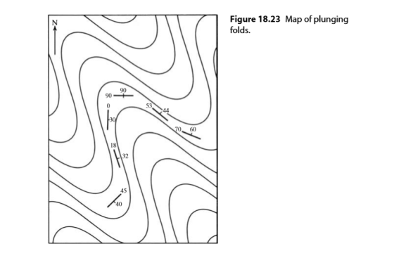
Determine the attitude of the fold axis of the folds shown in Fig. 18.23.
Homework Answers
Data from both the limbs (different colored planes on the plot)have been plotted in the stereonet and the intersection of the planes representing the limbs have been determined. This line of intersection gives the orientation of the fold axis.
Orientation of the fold axis 30°➡️90°(Plunge 30°, trend of the axis 90°)

Add Answer to:
Determine the attitude of the fold axis of the folds shown in Fig. 18.23.
P.25.14. Determine the axial force in the flanges and web of the channel section shown in...
 P.25.14. Determine the axial force in the flanges and web of the channel section shown in Fig. P.25.14 when it is subjected to a total axial force of 40 kN. The ply properties are E;= 140 000 N/mm², E,= 10 000 N/mm², G = 5000 N/mm² and v=0.3. Answer: Flange; 17.2 kN, Web; 5.6 kN. | 1.0 mm ----0.5 mm Flange layup (0/45/-45/90] 200 mm Web layup [45/-45] 11.0 mm 100 mm FIGURE P.25.14
The variation of the electric potential with position along the x-axis is shown in the figure...
 The variation of the electric potential with position along the x-axis is shown in the figure below. true about the this plot? Which of the following statements is 100 80 60 40 20 0 2 3 45 6789 10 Position [meters] Part C Determine the magnitude of the electric field at the position x-4 m Enter answer here V/m 18560 Your 18560V/mAnswe CHECK ANSWER 3 of 6 attempts used
Determine the force in each member of the scissors truss shown in Fig. 3-21a. State whether the members are in tens...
 Determine the force in each member of the scissors truss shown in Fig. 3-21a. State whether the members are in tension or compression. The reactions at the supports are 175 lb to C given. 200 Ib A;-141.4 lb 60° 45 ES 60 E 30 30° 10 ft -10 ft A, 125.4 lb E - 191.0 lb (a) Fig. 3-21 FED FEF E 15° 30 191.0 lb (b) Foc 75° D FoF 639.1 lb (c) 175 lb FCB 45T 639.1 Ib...
Determine the magnitude of the resultant and the angle that makes with positive X-axis. 150 lb...
 Determine the magnitude of the resultant and the angle that makes with positive X-axis. 150 lb F = 75cos (45)% = 53:03 F: Isocos (90°: 0 F3= 90 cos (105)=-23.29 Fy: 200 COS (180)° -200 fo=250 (05 (250) 85.5 90 lb 30 200 lb 52501b
For a unity feedback system as shown in Fig. 1, where 10(92 - 2s+2) G(8) =...
 For a unity feedback system as shown in Fig. 1, where 10(92 - 2s+2) G(8) = (5+1)(+ 2s +1) the Nyquist plot is shown in Figure 2 (a) Complete the Nyquist stability analysis for the system (b) If the system becomes G(s) = - 10(32 +28+2) (8 + 1)(s2 - 2s + 1)' with the Nyquist plot shown in Figure 3, is the closed-loop system stable? Complete the Nyquist stability analysis on this system. Figure 1: Pre- Imaginary Axis Imaginary...
Determine the forces acting in all the members of the truss shown in Fig. 6–9a ....
 Determine the forces acting in all the members of the truss
shown in Fig. 6–9a
.
I need help understanding the bold parts below of
the solution. Please explain the methods/math involved with
steps:
Joint C
.Fx=0;
- FCD cos 30 + FCB sin 45=0
Fy=0;
1.5 kN + FCD sin 30 - FCB cos 45=0
These two equations must be solved simultaneously for
each of the two unknowns. Note, however, that a direct solution for
one of the unknown...
Determine the forces acting in all the members of the truss
shown in Fig. 6–9a
.
I need help understanding the bold parts below of
the solution. Please explain the methods/math involved with
steps:
Joint C
.Fx=0;
- FCD cos 30 + FCB sin 45=0
Fy=0;
1.5 kN + FCD sin 30 - FCB cos 45=0
These two equations must be solved simultaneously for
each of the two unknowns. Note, however, that a direct solution for
one of the unknown...
Problem 1 For the cantilever retaining wall shown in Fig. 1, determine the factor of safety...
 Problem 1 For the cantilever retaining wall shown in Fig. 1, determine the factor of safety with respect to overturning, sliding, and bearing capacity. Use Rankine method to calculate the earth pressure. 18 in 100 Fig. 1 7 = 117 pcf (= 340 C = 0 4ft 30 in 6ft y = 110 pcf = 18 C = 800 psf
I) Determine the net torque on the 2.0-m-long uniform beam shown in Fig. 8–45. All forces...
 I) Determine the net torque on the 2.0-m-long uniform beam shown
in Fig. 8–45. All forces are shown. Calculate about (a) point C,
the CM, and (b) point P at one end.
56 N 32° 65 N 450 с P 58° 52 N © 2014 Pearson Education, Inc.
I) Determine the net torque on the 2.0-m-long uniform beam shown
in Fig. 8–45. All forces are shown. Calculate about (a) point C,
the CM, and (b) point P at one end.
56 N 32° 65 N 450 с P 58° 52 N © 2014 Pearson Education, Inc.
The arrangement EXERCISES 400 120 us 3 The arrangements of a transmission brake is shown in Fig. 19.40. The arms are...
 The arrangement
EXERCISES 400 120 us 3 The arrangements of a transmission brake is shown in Fig. 19.40. The arms are pivoted at o, and O2 and when force is applied at the end of a hand lever, the screw AB rotates. The left and right hand 120 force on the hand lever is applied 400 mm from the axis of the screw The drum is 240 mm in diameter and the angle subtended by each is 90°. The screw...
The arrangement
EXERCISES 400 120 us 3 The arrangements of a transmission brake is shown in Fig. 19.40. The arms are pivoted at o, and O2 and when force is applied at the end of a hand lever, the screw AB rotates. The left and right hand 120 force on the hand lever is applied 400 mm from the axis of the screw The drum is 240 mm in diameter and the angle subtended by each is 90°. The screw...
Ouestion 1 (10%) The circuit shown in Fig. 1 is at steady state before t-0s. Determine...
 Ouestion 1 (10%) The circuit shown in Fig. 1 is at steady state before t-0s. Determine v(t) and i(t) for>0. 3Ω 60 |(t) 12 u() 22 ) 12Ω Fig. 1
 P.25.14. Determine the axial force in the flanges and web of the channel section shown in Fig. P.25.14 when it is subjected to a total axial force of 40 kN. The ply properties are E;= 140 000 N/mm², E,= 10 000 N/mm², G = 5000 N/mm² and v=0.3. Answer: Flange; 17.2 kN, Web; 5.6 kN. | 1.0 mm ----0.5 mm Flange layup (0/45/-45/90] 200 mm Web layup [45/-45] 11.0 mm 100 mm FIGURE P.25.14
 The variation of the electric potential with position along the x-axis is shown in the figure below. true about the this plot? Which of the following statements is 100 80 60 40 20 0 2 3 45 6789 10 Position [meters] Part C Determine the magnitude of the electric field at the position x-4 m Enter answer here V/m 18560 Your 18560V/mAnswe CHECK ANSWER 3 of 6 attempts used
 Determine the force in each member of the scissors truss shown in Fig. 3-21a. State whether the members are in tension or compression. The reactions at the supports are 175 lb to C given. 200 Ib A;-141.4 lb 60° 45 ES 60 E 30 30° 10 ft -10 ft A, 125.4 lb E - 191.0 lb (a) Fig. 3-21 FED FEF E 15° 30 191.0 lb (b) Foc 75° D FoF 639.1 lb (c) 175 lb FCB 45T 639.1 Ib...
 Determine the magnitude of the resultant and the angle that makes with positive X-axis. 150 lb F = 75cos (45)% = 53:03 F: Isocos (90°: 0 F3= 90 cos (105)=-23.29 Fy: 200 COS (180)° -200 fo=250 (05 (250) 85.5 90 lb 30 200 lb 52501b
 For a unity feedback system as shown in Fig. 1, where 10(92 - 2s+2) G(8) = (5+1)(+ 2s +1) the Nyquist plot is shown in Figure 2 (a) Complete the Nyquist stability analysis for the system (b) If the system becomes G(s) = - 10(32 +28+2) (8 + 1)(s2 - 2s + 1)' with the Nyquist plot shown in Figure 3, is the closed-loop system stable? Complete the Nyquist stability analysis on this system. Figure 1: Pre- Imaginary Axis Imaginary...
 Determine the forces acting in all the members of the truss
shown in Fig. 6–9a
.
I need help understanding the bold parts below of
the solution. Please explain the methods/math involved with
steps:
Joint C
.Fx=0;
- FCD cos 30 + FCB sin 45=0
Fy=0;
1.5 kN + FCD sin 30 - FCB cos 45=0
These two equations must be solved simultaneously for
each of the two unknowns. Note, however, that a direct solution for
one of the unknown...
Determine the forces acting in all the members of the truss
shown in Fig. 6–9a
.
I need help understanding the bold parts below of
the solution. Please explain the methods/math involved with
steps:
Joint C
.Fx=0;
- FCD cos 30 + FCB sin 45=0
Fy=0;
1.5 kN + FCD sin 30 - FCB cos 45=0
These two equations must be solved simultaneously for
each of the two unknowns. Note, however, that a direct solution for
one of the unknown...
 Problem 1 For the cantilever retaining wall shown in Fig. 1, determine the factor of safety with respect to overturning, sliding, and bearing capacity. Use Rankine method to calculate the earth pressure. 18 in 100 Fig. 1 7 = 117 pcf (= 340 C = 0 4ft 30 in 6ft y = 110 pcf = 18 C = 800 psf
 I) Determine the net torque on the 2.0-m-long uniform beam shown
in Fig. 8–45. All forces are shown. Calculate about (a) point C,
the CM, and (b) point P at one end.
56 N 32° 65 N 450 с P 58° 52 N © 2014 Pearson Education, Inc.
I) Determine the net torque on the 2.0-m-long uniform beam shown
in Fig. 8–45. All forces are shown. Calculate about (a) point C,
the CM, and (b) point P at one end.
56 N 32° 65 N 450 с P 58° 52 N © 2014 Pearson Education, Inc.
 The arrangement
EXERCISES 400 120 us 3 The arrangements of a transmission brake is shown in Fig. 19.40. The arms are pivoted at o, and O2 and when force is applied at the end of a hand lever, the screw AB rotates. The left and right hand 120 force on the hand lever is applied 400 mm from the axis of the screw The drum is 240 mm in diameter and the angle subtended by each is 90°. The screw...
The arrangement
EXERCISES 400 120 us 3 The arrangements of a transmission brake is shown in Fig. 19.40. The arms are pivoted at o, and O2 and when force is applied at the end of a hand lever, the screw AB rotates. The left and right hand 120 force on the hand lever is applied 400 mm from the axis of the screw The drum is 240 mm in diameter and the angle subtended by each is 90°. The screw...
 Ouestion 1 (10%) The circuit shown in Fig. 1 is at steady state before t-0s. Determine v(t) and i(t) for>0. 3Ω 60 |(t) 12 u() 22 ) 12Ω Fig. 1
Most questions answered within 3 hours.
-
Calculate the moment
of inertia (in kg·m2) of a skater given the following
information.
(a)
The...
asked 1 minute ago -
A small body of mass m performs small oscillations sliding (no
rolling) along the bottom of...
asked 5 minutes ago -
The electric field in the region between two oppositely charged,
parallel, conducting plates has a magnitude...
asked 4 minutes ago -
A simple random sample was taken to test the claim that the
population mean is no...
asked 1 hour ago -
A set of length measurements are obtained with the values 165.6
± 0.3, 165.1± 0.4,166.4± 1.0,...
asked 1 hour ago -
1. Which of the following is true about unconscionable
contracts?
a. A term is substantially unconscionable...
asked 18 minutes ago -
A company is interested in estimating the costs of lunch
in their cafeteria. After surveying employees,...
asked 50 minutes ago -
A 0.2m diameter ball with an initial velocity of 8m/s rolls up a
hill without slipping....
asked 33 minutes ago -
I want to redraft the solution, using other words , use your own
words don't copy...
asked 22 minutes ago -
Hyundai Motors is considering threesites—A, B,C —at which to
locate a factory to build its new-model...
asked 24 minutes ago -
Learning Outcomes:
Upon the successful completion of this module, you should
understand the following concepts:
Strategic...
asked 25 minutes ago -
Identify four of the five major types of organizations within
the federal bureaucracy, and give examples...
asked 34 minutes ago