
Homework Answers


Add Answer to:
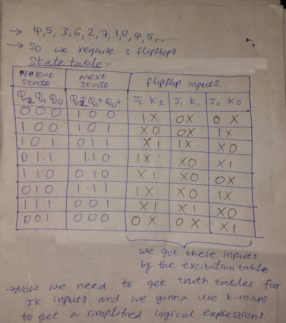
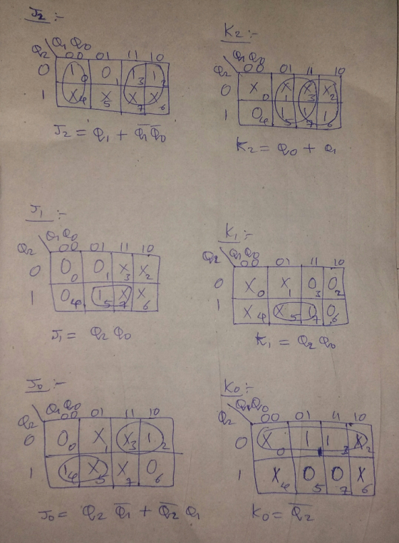
A counter to display the following sequence: 4,5,3,6, flip-flops in your design. Display the outp...
Design a counter that counts in the following sequence: 010, 011, 100, 101, and repeat. Use JK flip-flops in your implementation.
Design a counter that counts in the following sequence: 010, 011, 100, 101, and repeat. Use JK flip-flops in your implementation.
Design a counter circuit with sequence 0, 1, 2, …, 11 and repeat using JK flip-flops....
Design a counter circuit with sequence 0, 1, 2, …, 11 and repeat using JK flip-flops. Design the circuit with pen and paper and then simulate it using Logisim (justify the input values chosen)
Design a non-sequential synchronous counter using a positive edge triggered JK Flip Flops for the following...
 Design a non-sequential synchronous counter using a positive
edge triggered JK Flip Flops for the following output
0?2?3?5?4?7?6?0
Design a non-sequential synchronous counter using positive edge triggered JK Flip Flops for the following output 0 rightarrow 2 rightarrow 3 rightarrow 5 rightarrow 4 rightarrow 7 rightarrow 6 rightarrow 0
Design a non-sequential synchronous counter using a positive
edge triggered JK Flip Flops for the following output
0?2?3?5?4?7?6?0
Design a non-sequential synchronous counter using positive edge triggered JK Flip Flops for the following output 0 rightarrow 2 rightarrow 3 rightarrow 5 rightarrow 4 rightarrow 7 rightarrow 6 rightarrow 0
3. Design a counter with the following repeated binary sequence: 0,1,2,4,6. Use D flip-flop.
3. Design a counter with the following repeated binary sequence: 0,1,2,4,6. Use D flip-flop. 4. Design a counter to count with T flip-flops that goes through the following binary repeated sequence: 0,1,3,7,6,4. Find out the counter response towards the unused state. Illustrate the response with a state diagram. 5. Design a mod-7 counter (repeat binary sequence: 0,1,2,3,4,5,6) use JK flip-flop.
solve 1 2 and 3 Problems 1 and 2 require a 7-segment display. You may want to re-use the display driver you developed in Lab 3. Use a push-button as the clock - the pushbuttons are debounced, whereas...
 solve 1 2 and 3
Problems 1 and 2 require a 7-segment display. You may want to re-use the display driver you developed in Lab 3. Use a push-button as the clock - the pushbuttons are debounced, whereas the slide switches are not. Remember to provide columnsfor lest data in your state lables (use the observed next state as the test data in problems I and 2, and the observed next state and preseni output as the lest data in...
solve 1 2 and 3
Problems 1 and 2 require a 7-segment display. You may want to re-use the display driver you developed in Lab 3. Use a push-button as the clock - the pushbuttons are debounced, whereas the slide switches are not. Remember to provide columnsfor lest data in your state lables (use the observed next state as the test data in problems I and 2, and the observed next state and preseni output as the lest data in...
5) Using minimum possible of JK flip-flops design a counter that counts: 0, 3, 6, 1,...
 5) Using minimum possible of JK flip-flops design a counter that counts: 0, 3, 6, 1, 4, 7, 2, 0, ... (repeat). (10 Marks)
(a) Design an asynchronous Binary Coded Decimal (BCD) count-up counter using JK flip-flops. Draw the counter circuit clearly showing the configuration of the JK flip-flops and the necessary logic gat...
 (a) Design an asynchronous Binary Coded Decimal (BCD) count-up counter using JK flip-flops. Draw the counter circuit clearly showing the configuration of the JK flip-flops and the necessary logic gate(s). Sketch the input and output waveforms of this counter (7 Marks) (b) The binary up/down counter for a cargo lift controller in a 7-storey building has an up-down (UID) control input and a buzzer output (B). The buzzer will sound B 1) when the lift is at level 1 or...
A counter is designed to go through the sequence : 1,3,5,7,0,2,5,6, repeat, Using JK flip- flops:...
A counter is designed to go through the sequence : 1,3,5,7,0,2,5,6, repeat, Using JK flip- flops: (i) Construct the state table. (ii) Draw the circuit.
Up-Down counter with enable using JK flip-flops: Design, construct and test a 2-bit counter that counts up or down.
Up-Down counter with enable using JK flip-flops: Design, construct and test a 2-bit counter that counts up or down. An enable input E determines whether the counter is on or off. If E = 0, the counter is disabled and remains in the present count even though clock pulses are applied to the flip-flops. If E= 1, the counter in enabled and a second input, x, determines the count direction. If x= 1, the circuit counts up with the sequence...
Designa synchronous counter using jk flip flops with the following repeated sequence: 0,1,2,3
Designa synchronous counter using jk flip flops with the following repeated sequence: 0,1,2,3
 Design a non-sequential synchronous counter using a positive
edge triggered JK Flip Flops for the following output
0?2?3?5?4?7?6?0
Design a non-sequential synchronous counter using positive edge triggered JK Flip Flops for the following output 0 rightarrow 2 rightarrow 3 rightarrow 5 rightarrow 4 rightarrow 7 rightarrow 6 rightarrow 0
Design a non-sequential synchronous counter using a positive
edge triggered JK Flip Flops for the following output
0?2?3?5?4?7?6?0
Design a non-sequential synchronous counter using positive edge triggered JK Flip Flops for the following output 0 rightarrow 2 rightarrow 3 rightarrow 5 rightarrow 4 rightarrow 7 rightarrow 6 rightarrow 0
 solve 1 2 and 3
Problems 1 and 2 require a 7-segment display. You may want to re-use the display driver you developed in Lab 3. Use a push-button as the clock - the pushbuttons are debounced, whereas the slide switches are not. Remember to provide columnsfor lest data in your state lables (use the observed next state as the test data in problems I and 2, and the observed next state and preseni output as the lest data in...
solve 1 2 and 3
Problems 1 and 2 require a 7-segment display. You may want to re-use the display driver you developed in Lab 3. Use a push-button as the clock - the pushbuttons are debounced, whereas the slide switches are not. Remember to provide columnsfor lest data in your state lables (use the observed next state as the test data in problems I and 2, and the observed next state and preseni output as the lest data in...
 5) Using minimum possible of JK flip-flops design a counter that counts: 0, 3, 6, 1, 4, 7, 2, 0, ... (repeat). (10 Marks)
 (a) Design an asynchronous Binary Coded Decimal (BCD) count-up counter using JK flip-flops. Draw the counter circuit clearly showing the configuration of the JK flip-flops and the necessary logic gate(s). Sketch the input and output waveforms of this counter (7 Marks) (b) The binary up/down counter for a cargo lift controller in a 7-storey building has an up-down (UID) control input and a buzzer output (B). The buzzer will sound B 1) when the lift is at level 1 or...
Most questions answered within 3 hours.
-
Use proper sentence structure to communicate clearly.
Choose the correct sentence structure in each of the...
asked 50 seconds from now -
There are investors who claim they only invest in companies with
great products and outstanding management,...
asked 2 minutes ago -
what is employee/ employer relations ?
why is Employee/ Employer relation is important in the context...
asked 20 minutes ago -
Explain the relationship between tests of acquisition and
payment cycle and tests of accounts payable. Give...
asked 18 minutes ago -
A hot-air balloon is descending with a velocity of (−2.00m/s)y^.
A champagne bottle is opened to...
asked 37 minutes ago -
1. When a nearsighted person looks at an object that is in the
distance with their...
asked 1 hour ago -
QUESTION 8
Both of these statements will store the same value in the
variable $number
$number...
asked 2 hours ago -
The price of 1 lb of potatoes is $1.75. If all the potatoes sold
today at...
asked 3 hours ago -
Garcia Company issues 20.00%, 15-year bonds with a par value of
$470,000 and semiannual interest payments....
asked 3 hours ago -
In C++ Programming, Try using loops only.
This lab demonstrates the use of the While Loop...
asked 4 hours ago -
Effect of DCMU and sodium azide on Chlamydomonas? We did an
experiment where we had Chlamydomonas...
asked 4 hours ago -
1a) According to the ideal gas law, _______________.
a. a gas has infinite volume at absolute...
asked 6 hours ago