
Homework Answers

Add Answer to:
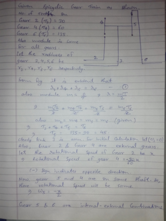
Problem 3:The figure shows the simplified designation of an elementary epicyclic gear train. Numb...
estion- a) Find the speed ratio of the gear train shown in figure. What will be...
 estion- a) Find the speed ratio of the gear train shown in figure. What will be the direction of gear 7 b) Determine pitch line velocity (v r.w) of gear &, provided for gear 6 Imodule (D/T) 5mm e) If double the speed ratio (as calculated in a) is required with a simple gear train (having only two gears) number of teeth on driven gear, provided input gear has 20 teeth. IST IST 25T 33T I8T An epicyclic gear train...
A compound epicyclic gear train is shown in the Figure. The shaft P is driven a...
 A compound epicyclic gear train is shown in the Figure. The
shaft P is driven a 4000 rpm in the clockwise direction by a motor
of power rating of 10W . The annulus A2 is fixed. The
number of teeth in the gears are , S1,28;
S2,21; A1,72 and A2,99 .
Determine:
The magnitude and direction of the angular velocity of the
shaft Q
The torque required to fix the annulus, A2
A, A₂ P, P2 P P. z S
A compound epicyclic gear train is shown in the Figure. The
shaft P is driven a 4000 rpm in the clockwise direction by a motor
of power rating of 10W . The annulus A2 is fixed. The
number of teeth in the gears are , S1,28;
S2,21; A1,72 and A2,99 .
Determine:
The magnitude and direction of the angular velocity of the
shaft Q
The torque required to fix the annulus, A2
A, A₂ P, P2 P P. z S
A compound epicyclic gear train is shown in the Figure. The shaft P is driven at...
 A compound epicyclic gear train is shown in the Figure. The
shaft P is driven at 2500 rpm in the clockwise direction by a motor
of power rating 8 kW. The sun S2 is fixed. The number of teeth in
the gears are S1, 34; S2, 21; A1, 86 and A2, 73. Determine
The magnitude and direction of the angular velocity of the
shaft Q and
The torque required to fix the sun, S2
A, Q P S, 5,
A compound epicyclic gear train is shown in the Figure. The
shaft P is driven at 2500 rpm in the clockwise direction by a motor
of power rating 8 kW. The sun S2 is fixed. The number of teeth in
the gears are S1, 34; S2, 21; A1, 86 and A2, 73. Determine
The magnitude and direction of the angular velocity of the
shaft Q and
The torque required to fix the sun, S2
A, Q P S, 5,
1. In an epicyclic gear train, as shown in Figure, the wheel C is keyed to...
 1. In an epicyclic gear train, as shown in Figure, the wheel C is keyed to the shaft B and wheel F is keyed to shaft A. The wheels D and E rotate together on a pin fixed to the arm G. The number of teeth on wheels C, D, E and F are 35, 65, 32 and 68 respectively. If the shaft A rotates at 60 rpm and the shaft B rotates at 28 rpm in the opposite direction,...
Homework 6: The figure below shows a gear train where gear 1, on shaft a (input...
 Homework 6: The figure below shows a gear train where gear 1, on shaft a (input shaft), drives gear 2 with 32 teeth (denoted 32T) on shaft b, gear 3 (20T) also is on shaft b and drives gear 4 (507) on shaft c (output shaft). The pitch diameter of gears 1 and 2 are d = 24 mm and d = 48 mm. The center distance between gears 3 and 4 (distance between shafts b and c is 70mm....
2. Fig.2 shows an epicyclic gear train in which the internal teeth on the gears A and B have the same diametral p...
 2. Fig.2 shows an epicyclic gear train in which the internal teeth on the gears A and B have the same diametral pitch. Gear A has 88 teeth and gear B has 100 teeth both internally and externally. The sun-wheel C which is keyed to shaft P has 44 teeth and the pinion E keyed to shaft R has 25. There are floating compound planet wheels F, G. The power input to shaft R is 8 kW at 1440 rev/min....
A gear train shown below has the following data: Z2- 18T, Z 72T Z 16T and...
 A gear train shown below has the following data: Z2- 18T, Z 72T Z 16T and Zs 48T. If gear 2 rotates at 1200 RPM (CWD) and transmit 10 kW power, find the following:- a- the center distance between gears 2 and 5 (gears' module- 5 mm). b- the velocity of gears5 c- bending stress resulted in gear 2 teeth. Assume reasonable face width for gears.
Figure Q1 shows a gear train consists of four spur gears A, B, C and D to be designed for a specific mechanism. The power transmitted by gear A is 5 kW at rotational speed of 720 rpm counterclockwise direction. Number of teeth (N) for gears A,B,C and D ar
 Figure Q1 shows a gear train consists of four spur gears A, B, C and D to be designed for a specific
mechanism. The power transmitted by gear A is 5 kW at rotational speed of 720 rpm
counterclockwise direction. Number of teeth (N) for gears A,B,C and D are respectively 20, 50,
30 and 60. The module and pressure angle of the gears are respectively 4 mm and 20o
. Determine
followings:
(a) Tangential and radial forces between gears...
Figure Q1 shows a gear train consists of four spur gears A, B, C and D to be designed for a specific
mechanism. The power transmitted by gear A is 5 kW at rotational speed of 720 rpm
counterclockwise direction. Number of teeth (N) for gears A,B,C and D are respectively 20, 50,
30 and 60. The module and pressure angle of the gears are respectively 4 mm and 20o
. Determine
followings:
(a) Tangential and radial forces between gears...
Kinematics class 3. (25 POINTS) Planetary gear train analysis: The figure below representsa planetary gear train...
 Kinematics class
3. (25 POINTS) Planetary gear train analysis: The figure below representsa planetary gear train used in a drill head. Gear 1 rotates with the input shaft. The ring gear 3 meshes both with gear 5 and gear 6, which are the planets. Gear 2 acts as the carrier for gear 5, the output is the carrier 4 Consider the number of teeth Ni-6, N2 36, N-54, N-24 and No-9 a) Identify how many stages are needed to fully...
Kinematics class
3. (25 POINTS) Planetary gear train analysis: The figure below representsa planetary gear train used in a drill head. Gear 1 rotates with the input shaft. The ring gear 3 meshes both with gear 5 and gear 6, which are the planets. Gear 2 acts as the carrier for gear 5, the output is the carrier 4 Consider the number of teeth Ni-6, N2 36, N-54, N-24 and No-9 a) Identify how many stages are needed to fully...
i want to get part c,d The figure below is a gear-train mechanical system driven by...
 i want to get part c,d
The figure below is a gear-train mechanical system driven by a prescribed motion in the form of an angular displacement y(t). The motion is caused by an applied torque T(t) generated by a motor. The mass moment of inertias of the motor and the driving gear are J and J, respectively, whereas the mass moment of inertias of the load and the driven gear are J, and J2, respectively. The radii and angular displacements...
i want to get part c,d
The figure below is a gear-train mechanical system driven by a prescribed motion in the form of an angular displacement y(t). The motion is caused by an applied torque T(t) generated by a motor. The mass moment of inertias of the motor and the driving gear are J and J, respectively, whereas the mass moment of inertias of the load and the driven gear are J, and J2, respectively. The radii and angular displacements...
 estion- a) Find the speed ratio of the gear train shown in figure. What will be the direction of gear 7 b) Determine pitch line velocity (v r.w) of gear &, provided for gear 6 Imodule (D/T) 5mm e) If double the speed ratio (as calculated in a) is required with a simple gear train (having only two gears) number of teeth on driven gear, provided input gear has 20 teeth. IST IST 25T 33T I8T An epicyclic gear train...
 A compound epicyclic gear train is shown in the Figure. The
shaft P is driven a 4000 rpm in the clockwise direction by a motor
of power rating of 10W . The annulus A2 is fixed. The
number of teeth in the gears are , S1,28;
S2,21; A1,72 and A2,99 .
Determine:
The magnitude and direction of the angular velocity of the
shaft Q
The torque required to fix the annulus, A2
A, A₂ P, P2 P P. z S
A compound epicyclic gear train is shown in the Figure. The
shaft P is driven a 4000 rpm in the clockwise direction by a motor
of power rating of 10W . The annulus A2 is fixed. The
number of teeth in the gears are , S1,28;
S2,21; A1,72 and A2,99 .
Determine:
The magnitude and direction of the angular velocity of the
shaft Q
The torque required to fix the annulus, A2
A, A₂ P, P2 P P. z S
 A compound epicyclic gear train is shown in the Figure. The
shaft P is driven at 2500 rpm in the clockwise direction by a motor
of power rating 8 kW. The sun S2 is fixed. The number of teeth in
the gears are S1, 34; S2, 21; A1, 86 and A2, 73. Determine
The magnitude and direction of the angular velocity of the
shaft Q and
The torque required to fix the sun, S2
A, Q P S, 5,
A compound epicyclic gear train is shown in the Figure. The
shaft P is driven at 2500 rpm in the clockwise direction by a motor
of power rating 8 kW. The sun S2 is fixed. The number of teeth in
the gears are S1, 34; S2, 21; A1, 86 and A2, 73. Determine
The magnitude and direction of the angular velocity of the
shaft Q and
The torque required to fix the sun, S2
A, Q P S, 5,
 1. In an epicyclic gear train, as shown in Figure, the wheel C is keyed to the shaft B and wheel F is keyed to shaft A. The wheels D and E rotate together on a pin fixed to the arm G. The number of teeth on wheels C, D, E and F are 35, 65, 32 and 68 respectively. If the shaft A rotates at 60 rpm and the shaft B rotates at 28 rpm in the opposite direction,...
 Homework 6: The figure below shows a gear train where gear 1, on shaft a (input shaft), drives gear 2 with 32 teeth (denoted 32T) on shaft b, gear 3 (20T) also is on shaft b and drives gear 4 (507) on shaft c (output shaft). The pitch diameter of gears 1 and 2 are d = 24 mm and d = 48 mm. The center distance between gears 3 and 4 (distance between shafts b and c is 70mm....
 2. Fig.2 shows an epicyclic gear train in which the internal teeth on the gears A and B have the same diametral pitch. Gear A has 88 teeth and gear B has 100 teeth both internally and externally. The sun-wheel C which is keyed to shaft P has 44 teeth and the pinion E keyed to shaft R has 25. There are floating compound planet wheels F, G. The power input to shaft R is 8 kW at 1440 rev/min....
 A gear train shown below has the following data: Z2- 18T, Z 72T Z 16T and Zs 48T. If gear 2 rotates at 1200 RPM (CWD) and transmit 10 kW power, find the following:- a- the center distance between gears 2 and 5 (gears' module- 5 mm). b- the velocity of gears5 c- bending stress resulted in gear 2 teeth. Assume reasonable face width for gears.
 Kinematics class
3. (25 POINTS) Planetary gear train analysis: The figure below representsa planetary gear train used in a drill head. Gear 1 rotates with the input shaft. The ring gear 3 meshes both with gear 5 and gear 6, which are the planets. Gear 2 acts as the carrier for gear 5, the output is the carrier 4 Consider the number of teeth Ni-6, N2 36, N-54, N-24 and No-9 a) Identify how many stages are needed to fully...
Kinematics class
3. (25 POINTS) Planetary gear train analysis: The figure below representsa planetary gear train used in a drill head. Gear 1 rotates with the input shaft. The ring gear 3 meshes both with gear 5 and gear 6, which are the planets. Gear 2 acts as the carrier for gear 5, the output is the carrier 4 Consider the number of teeth Ni-6, N2 36, N-54, N-24 and No-9 a) Identify how many stages are needed to fully...
 i want to get part c,d
The figure below is a gear-train mechanical system driven by a prescribed motion in the form of an angular displacement y(t). The motion is caused by an applied torque T(t) generated by a motor. The mass moment of inertias of the motor and the driving gear are J and J, respectively, whereas the mass moment of inertias of the load and the driven gear are J, and J2, respectively. The radii and angular displacements...
i want to get part c,d
The figure below is a gear-train mechanical system driven by a prescribed motion in the form of an angular displacement y(t). The motion is caused by an applied torque T(t) generated by a motor. The mass moment of inertias of the motor and the driving gear are J and J, respectively, whereas the mass moment of inertias of the load and the driven gear are J, and J2, respectively. The radii and angular displacements...
Most questions answered within 3 hours.
-
#include <iostream>
#include <vector>
using namespace std;
class Solution {
public:
vector<int> smallerNumbersThanCurrent(vector<int>&
nums) {
int...
asked 6 minutes ago -
1) What 8 guidelines should you follow to enable you to use
email efficiently and effectively...
asked 9 minutes ago -
What geographical obstacle seems to have taken the longest time
for modern humans to get across?...
asked 14 minutes ago -
When Maria Acosta bought a car 2 and a half
years ago, she borrowed $11,000 for...
asked 23 minutes ago -
package rectangle;
public class Rectangle {
private int height;
private int width;
public...
asked 24 minutes ago -
The Yankee's have a contract with their newly hired manager that
requires a lump sum payment...
asked 44 minutes ago -
A travelling salesman sells milkshake mixing machines and on
average sells 8.9 machines per month. He...
asked 49 minutes ago -
what's the danger in the fact that the market value of a stock
is based on...
asked 1 hour ago -
Describe how do you feel about the post below and
why?
Listening to the podcast reaffirmed...
asked 1 hour ago -
To start an avalanche on a mountain slope, an artillery shell is
fired with an initial...
asked 1 hour ago -
The population of bacteria in a culture can be modeled by P left
parenthesis t right...
asked 1 hour ago -
Which factors can prevent permanent fixation of an allele (i.e.
maintain genetic diversity)? Hint: You're going...
asked 1 hour ago