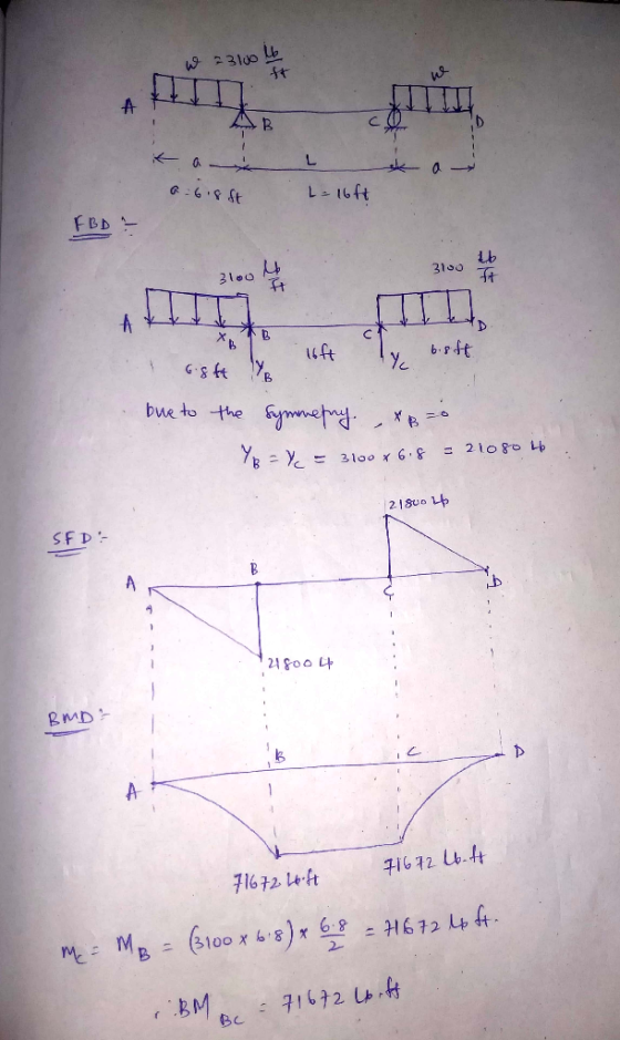
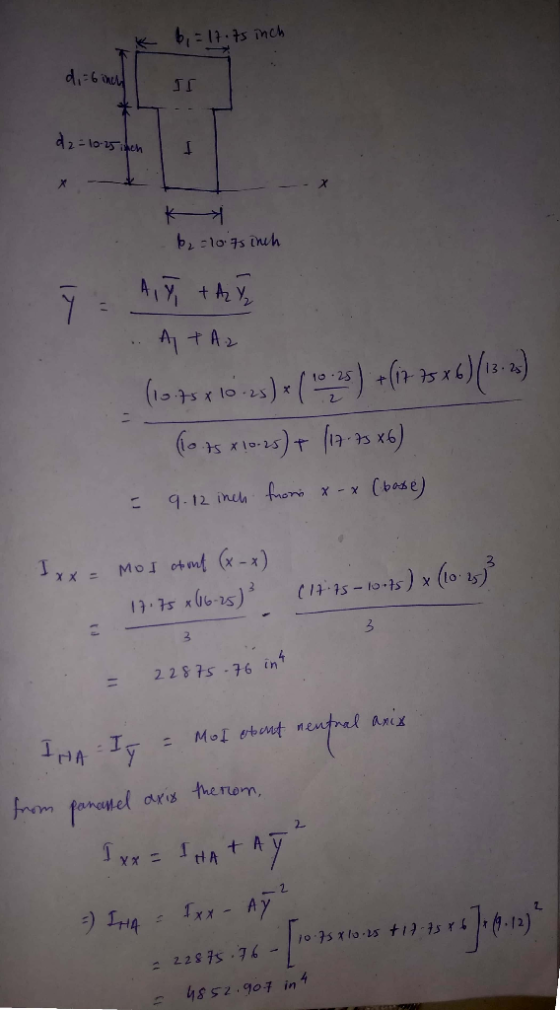
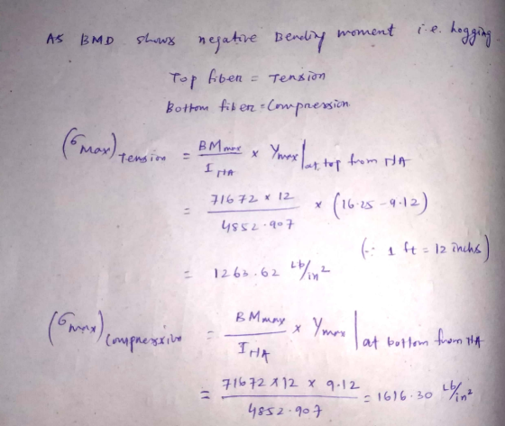
a) Two uniformly distributed loads of w=3100 lb/ft act on the simply supported beam shown in Figure A. The beam spans are a=6.8 ft and L=16.0 ft. The beam cross section shown in Figure B has dimensions of b1=17.75 in., d1=6.00 in., b2=10.75 in., and d2=10.25 in. Calculate the maximum tensile and compressive bending stresses produced in segment BC of the beam.
Homework Answers
Add Answer to:
A) Two uniformly distributed loads of w=3100 lb/ft act on the simply supported beam shown in Figu...
a simply supported beam is loaded by a uniformly distributed load of 200 lb/ft as shown...
 a simply supported beam is loaded by a uniformly distributed
load of 200 lb/ft as shown in the figure. the cross section is made
of many wooden pieces as shown. given that the lag screws to be
used are ½ in in diameter and the allowable shear force in each lag
screw is 500 lb, determine the longitudinal spacing required for
lag screws at a and b. also, find the displacement and rotation at
5 ft.
10in NA. 4in Sin...
a simply supported beam is loaded by a uniformly distributed
load of 200 lb/ft as shown in the figure. the cross section is made
of many wooden pieces as shown. given that the lag screws to be
used are ½ in in diameter and the allowable shear force in each lag
screw is 500 lb, determine the longitudinal spacing required for
lag screws at a and b. also, find the displacement and rotation at
5 ft.
10in NA. 4in Sin...
P8.013 (GO Tutorial) Your answer is partially correct. Try again. Two unformly distibuted loads of w4100...
 P8.013 (GO Tutorial) Your answer is partially correct. Try again. Two unformly distibuted loads of w4100 lb/ft act on the simply supported beam shown in Fiure A. The beam spans are a 8.7 ft and L15.7 ft. The beam cross section shown in Figure D has dimensions of b16.00n., d 5.75 in,12.00 in., and 10.75 in. Calculate the maximum tensile and compressive bending stresses produced in segment BC of the beam FIGUREA bi s. FIGURE B Ơteisile- ธ.impresive-T3184.477 Click if...
Chapter 15, Supplemental Question 121 The simply supported beam supports a uniformly distributed load of w-300...
 Chapter 15, Supplemental Question 121 The simply supported beam supports a uniformly distributed load of w-300 lb/ft between supports A and B and a concentrated load of P = 2165 lb at end C. The cross-sectional dimensions of the beam shown in the second figure are b 12 in., t2.50 in.,d-11 in., and tw-2.50 in. Using L-14 ft and xK3 ft, determine the principal stresses and the maximum shear stress acting at point K, which is located at a distance...
100 lb/tht A cantilever beam 10 ft long carries a uniformly distributed load of w 100...
 100 lb/tht A cantilever beam 10 ft long carries a uniformly distributed load of w 100 lb/ft. The beam is constructed from a 3-in.-wide by 8-in.-deep wood timber (1) that is reinforced on its upper surface by a 3-in.-wide by 0.25-in.-thick alumi- 3im num plate (2). The elastic modulus of the wood is E 1,700 ksi, and the elastic modulus of the aluminum plate is E 10,200 ksi. Determine 0h Cross-sectional dimensions. the maximum bending stresses produced in timber (1)...
A steel I-section beam, simply supported at its two ends, is subjected to a uniformly distributed...
 A steel I-section beam, simply supported at its two ends, is
subjected to a uniformly distributed load q (vertically downward)
over its central segment having a length of 2 m as shown in the
figure. It also shows the type of restraints (F/P/L) against
lateral torsional buckling of the beam at its four sections. The
section at the left end of the beam has only the lateral rotational
restraint. The load is causing bending of the beam about x-x (major...
A steel I-section beam, simply supported at its two ends, is
subjected to a uniformly distributed load q (vertically downward)
over its central segment having a length of 2 m as shown in the
figure. It also shows the type of restraints (F/P/L) against
lateral torsional buckling of the beam at its four sections. The
section at the left end of the beam has only the lateral rotational
restraint. The load is causing bending of the beam about x-x (major...
2. A 30 ft long simply supported beam supports a uniformly distributed load of 2 kips/ft...
 2. A 30 ft long simply supported beam supports a uniformly distributed load of 2 kips/ft over the entire span. The beam and cross section are shown below. Draw the shear and moment diagrams, find the neutral axis location, moment of inertia of the composite section, the maximum bending stress on the cross section. (40 points) 10" 2 k/ft 1-3" 30'-0"
Problem 3 (19 points): A simply supported beam ABCD carries a uniformly distributed load, w, and...
 Problem 3 (19 points): A simply supported beam ABCD carries a uniformly distributed load, w, and a concentrated load, F, as shown in the figure. All the dimensions are given in the figure, and the weight of the beam is neglected a) Draw the free body diagram for the beam, showing all the applied and reaction forces. Find the reaction forces F=14 kN .6m b) Give the expression for the shear force, V- V(x), and the bending moment M M(x),...
The simply supported beam of length L is subjected to uniformly distributed load of w and...
 The simply supported beam of length L is subjected to uniformly distributed load of w and a vertical point load P at its middle, as shown in Figure Q3. Both young's modulus and second moment of area of this structure are given as E and I. Please provide your answers in terms of letters w, P,L,1, E. Self-weight of the beam is neglected. P W L/2 L/2 Figure Q3 (a) Determine the reactions, bending moment equation along the beam and...
The simply-supported beam having I-beam cross-section as shown in figure is to carry a uniformly distributed...
 The simply-supported beam having I-beam cross-section as shown in figure is to carry a uniformly distributed load over its entire 1.2m length. Specify the maximum allowable load if the beam is made from malleable iron, ASTM A220, class 80002. The allowable tensile stress is 164 MPa and allowable compressive stress is 412 MPa. The centroid of the section is located at 35 mm from the bottom and moment of inertia are Ix = 2.66 x 10 mm". (a) Draw loading...
Chapter 8, Supplemental Question 067 (Go Tutorial) The simply supported beam shown carries a uniformly distributed...
 Chapter 8, Supplemental Question 067 (Go Tutorial) The simply supported beam shown carries a uniformly distributed load of w 28 kN/m on overhang BC. The beam is constructed of a Southern pine [E 12 GPa] timber that is reinforced on its upper surface by a steel [E-200 GPa] plate as shown. The beam spans are LAB-4.5 m and Lec-1.25 m. The wood beam has dimensions of bw-230 mm and dw-310 mm. The steel plate dimensions are bs - 245 mm...
 a simply supported beam is loaded by a uniformly distributed
load of 200 lb/ft as shown in the figure. the cross section is made
of many wooden pieces as shown. given that the lag screws to be
used are ½ in in diameter and the allowable shear force in each lag
screw is 500 lb, determine the longitudinal spacing required for
lag screws at a and b. also, find the displacement and rotation at
5 ft.
10in NA. 4in Sin...
a simply supported beam is loaded by a uniformly distributed
load of 200 lb/ft as shown in the figure. the cross section is made
of many wooden pieces as shown. given that the lag screws to be
used are ½ in in diameter and the allowable shear force in each lag
screw is 500 lb, determine the longitudinal spacing required for
lag screws at a and b. also, find the displacement and rotation at
5 ft.
10in NA. 4in Sin...
 P8.013 (GO Tutorial) Your answer is partially correct. Try again. Two unformly distibuted loads of w4100 lb/ft act on the simply supported beam shown in Fiure A. The beam spans are a 8.7 ft and L15.7 ft. The beam cross section shown in Figure D has dimensions of b16.00n., d 5.75 in,12.00 in., and 10.75 in. Calculate the maximum tensile and compressive bending stresses produced in segment BC of the beam FIGUREA bi s. FIGURE B Ơteisile- ธ.impresive-T3184.477 Click if...
 Chapter 15, Supplemental Question 121 The simply supported beam supports a uniformly distributed load of w-300 lb/ft between supports A and B and a concentrated load of P = 2165 lb at end C. The cross-sectional dimensions of the beam shown in the second figure are b 12 in., t2.50 in.,d-11 in., and tw-2.50 in. Using L-14 ft and xK3 ft, determine the principal stresses and the maximum shear stress acting at point K, which is located at a distance...
 100 lb/tht A cantilever beam 10 ft long carries a uniformly distributed load of w 100 lb/ft. The beam is constructed from a 3-in.-wide by 8-in.-deep wood timber (1) that is reinforced on its upper surface by a 3-in.-wide by 0.25-in.-thick alumi- 3im num plate (2). The elastic modulus of the wood is E 1,700 ksi, and the elastic modulus of the aluminum plate is E 10,200 ksi. Determine 0h Cross-sectional dimensions. the maximum bending stresses produced in timber (1)...
 A steel I-section beam, simply supported at its two ends, is
subjected to a uniformly distributed load q (vertically downward)
over its central segment having a length of 2 m as shown in the
figure. It also shows the type of restraints (F/P/L) against
lateral torsional buckling of the beam at its four sections. The
section at the left end of the beam has only the lateral rotational
restraint. The load is causing bending of the beam about x-x (major...
A steel I-section beam, simply supported at its two ends, is
subjected to a uniformly distributed load q (vertically downward)
over its central segment having a length of 2 m as shown in the
figure. It also shows the type of restraints (F/P/L) against
lateral torsional buckling of the beam at its four sections. The
section at the left end of the beam has only the lateral rotational
restraint. The load is causing bending of the beam about x-x (major...
 2. A 30 ft long simply supported beam supports a uniformly distributed load of 2 kips/ft over the entire span. The beam and cross section are shown below. Draw the shear and moment diagrams, find the neutral axis location, moment of inertia of the composite section, the maximum bending stress on the cross section. (40 points) 10" 2 k/ft 1-3" 30'-0"
 Problem 3 (19 points): A simply supported beam ABCD carries a uniformly distributed load, w, and a concentrated load, F, as shown in the figure. All the dimensions are given in the figure, and the weight of the beam is neglected a) Draw the free body diagram for the beam, showing all the applied and reaction forces. Find the reaction forces F=14 kN .6m b) Give the expression for the shear force, V- V(x), and the bending moment M M(x),...
 The simply supported beam of length L is subjected to uniformly distributed load of w and a vertical point load P at its middle, as shown in Figure Q3. Both young's modulus and second moment of area of this structure are given as E and I. Please provide your answers in terms of letters w, P,L,1, E. Self-weight of the beam is neglected. P W L/2 L/2 Figure Q3 (a) Determine the reactions, bending moment equation along the beam and...
 The simply-supported beam having I-beam cross-section as shown in figure is to carry a uniformly distributed load over its entire 1.2m length. Specify the maximum allowable load if the beam is made from malleable iron, ASTM A220, class 80002. The allowable tensile stress is 164 MPa and allowable compressive stress is 412 MPa. The centroid of the section is located at 35 mm from the bottom and moment of inertia are Ix = 2.66 x 10 mm". (a) Draw loading...
 Chapter 8, Supplemental Question 067 (Go Tutorial) The simply supported beam shown carries a uniformly distributed load of w 28 kN/m on overhang BC. The beam is constructed of a Southern pine [E 12 GPa] timber that is reinforced on its upper surface by a steel [E-200 GPa] plate as shown. The beam spans are LAB-4.5 m and Lec-1.25 m. The wood beam has dimensions of bw-230 mm and dw-310 mm. The steel plate dimensions are bs - 245 mm...
Most questions answered within 3 hours.
-
Michaella, age 23, is a full-time law student and is claimed by
her parents as a...
asked 15 seconds from now -
Why are polymers not typically casted into products?
asked 16 minutes ago -
When rolling a die 129 times, what is the probability of rolling
a 6 no more...
asked 33 minutes ago -
4. A call option currently sells for $7.75. It has a strike
price of $85 and...
asked 22 minutes ago -
1.
You need to prepare 10.0 liters of an acid aqueous solution with a
pH of...
asked 24 minutes ago -
Along an aggregate supply curve, if the level of output is less
than the natural level...
asked 25 minutes ago -
By 2025, annual consumption in emerging markets will total $30
trillion and contribute more than ________...
asked 30 minutes ago -
At what point does reformation cease to be a viable option for
those who are oppressed...
asked 34 minutes ago -
Place letters corresponding to amounts in the proper order for
lightest to heaviest samples:
a) 2100...
asked 38 minutes ago -
Consider the multicore processor with 6 heterogeneous cores
labelled C1, C2, C3, C4, C5, and C6....
asked 41 minutes ago -
Document system components according to standards and procedures
(Implement and hand over system components) IT administrative
asked 41 minutes ago -
The college asked 700 students if they wanted a longer spring
break and 600 students said...
asked 41 minutes ago