 Can anyone explain how can you
get the above logic diagram? I have no clue how the answer is like
that. I've been trying to derive the truth table and draw the logic
diagram, but it's not the same as the above answer.
Can anyone explain how can you
get the above logic diagram? I have no clue how the answer is like
that. I've been trying to derive the truth table and draw the logic
diagram, but it's not the same as the above answer.
Draw the logic diagram of a circuit implementing the Moore Machine of 1). 3 2 D Q D Q D a clk Draw the logic diagram of a circuit implementing the Moore Machine of I). You can use T flip-flops only 4 clk
Homework Answers
The logic circuit given here is not at all following conventional
method of designing
fsm technique.
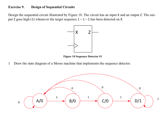
Looking in to the state diagram, A, B, C and D are defined states.
If we use binary state encoding then we need two flip flops (Q1Q0 = 00 = A, 01 = B, 10 = C and D = 11)
If we use one hot state encoding then we need four flip flops (Q3Q2Q1Q0 = 0001 = A, 0010 = B, 0100 = C and 1000 = D)
Hence given circuit is based on characteristics of D / T Flip Flops.
Circuit given in Q3 is simple 3 bit right shift register,
Output Z, is Q2 AND Q1 AND Q0. Hence if X input is 111 then only in 3 consecutive clock ticks Q2Q1Q0 = 111 causing Z = 1.
Q4.
To understand, Let us assume initially Q2Q1Q0 = 000.
Now if X = 1 then, at
@ first clock tick, Q0 = 1, Q1 = 0, Q2 = 0
Again if X = 1
@ second clock tick, Q0 = 1, Q1 = 1, Q2 = 0
Similarly if still X = 1, then
@ third clock tic, Q0 = 1, Q1 = 1, Q2 = 1 causing Z = 1 (111 detected)
Here remember that T Flip Flop output toggles its output if its T input = 1
Hence essentially both circuits are shift registers.
Add Answer to:
Can anyone explain how can you get the above logic diagram? I have no clue how the answer is like that. I've been trying to derive the truth table and draw the logic diagram, but it's not the...
please provide the answers of the 4 points thanks? C Tarek Ould-Bachir, PEng,PhD. Design of Sequential Circuits ise 10. nesign the sequential circuit illustrated by Figure 11 Sequence Detector. Th...
 please provide the answers of the 4 points thanks?
C Tarek Ould-Bachir, PEng,PhD. Design of Sequential Circuits ise 10. nesign the sequential circuit illustrated by Figure 11 Sequence Detector. The cireuit has an input X and wo outputs Y and Z. The output Y goes high (1) whenever the sequence 1-0-1 has been detected on x. The output Z goes high (1) whenever the sequence 1-1 has been detected on X. Figure 11 Sequence Detector #2 1 Draw the state...
please provide the answers of the 4 points thanks?
C Tarek Ould-Bachir, PEng,PhD. Design of Sequential Circuits ise 10. nesign the sequential circuit illustrated by Figure 11 Sequence Detector. The cireuit has an input X and wo outputs Y and Z. The output Y goes high (1) whenever the sequence 1-0-1 has been detected on x. The output Z goes high (1) whenever the sequence 1-1 has been detected on X. Figure 11 Sequence Detector #2 1 Draw the state...
Draw a Moore-type state diagram and design a synchronous sequential circuit using D flip flops for...
Draw a Moore-type state diagram and design a synchronous sequential circuit using D flip flops for a 1-input/1-output "sequence detector" for the sequence 110 (be sure to recognize overlapping sequences). Draw the final circuit.
Draw a Moore-type state diagram and design a synchronous sequential circuit using D flip flops for...
Draw a Moore-type state diagram and design a synchronous sequential circuit using D flip flops for a 1-input/1-output "sequence detector" for the sequence 1001 (be sure to recognize overlapping sequences). Draw the final circuit.
Please send an easy to read circuit design as well and explain how it works. 4:02...
 Please send an easy to read circuit design as well and explain
how it works.
4:02 00 LTE il 50% + ENEE 2586 - Lab 9_f... @ + : ENEF 356 Lab -Sequence Detector ENEE 2586 Lab #9 - Sequence Detector Purpose: The goal of this lab is to design a sequence detector using sequential logic circuits Procedure: 1. Design a sequential logic circuit to check an input stream labeled X and to produce an output Z=1 for any input...
Please send an easy to read circuit design as well and explain
how it works.
4:02 00 LTE il 50% + ENEE 2586 - Lab 9_f... @ + : ENEF 356 Lab -Sequence Detector ENEE 2586 Lab #9 - Sequence Detector Purpose: The goal of this lab is to design a sequence detector using sequential logic circuits Procedure: 1. Design a sequential logic circuit to check an input stream labeled X and to produce an output Z=1 for any input...
Can I get the chance to do this please ? A sequential circuit has an input...
Can I get the chance to do this please ? A sequential circuit has an input w and an output z (and an input reset). Its function is to generate z = 1 when the binary sequence 010 is detected; otherwise, z = 0. Implement the circuit in a Moore machine using graphical symbols of D flip-flops and any other gates. You can use a straightforward assignment method. An example of the desired behavior is as follows w: 010101010011001011 z:...
Can I please get the answers for these questions ASAP. Please. Design a 8x128 FIFO (8...
 Can I please get the answers for these questions ASAP.
Please.
Design a 8x128 FIFO (8 bits wide, 128 locations) with Almost Full, Full and Empty Flags. 1. Use Finite State Machine design techniques in VHDL 2. Design a testbench around this and run in the lab, print the waveforms. Design a sequence detector where a string of "110" on a serial input data port (A) is detected and output Z is set to 1 . Design will have input...
Can I please get the answers for these questions ASAP.
Please.
Design a 8x128 FIFO (8 bits wide, 128 locations) with Almost Full, Full and Empty Flags. 1. Use Finite State Machine design techniques in VHDL 2. Design a testbench around this and run in the lab, print the waveforms. Design a sequence detector where a string of "110" on a serial input data port (A) is detected and output Z is set to 1 . Design will have input...
5) Decoders: Given the following circuit, S0 and S1 are computed using a 4-2 priority encoder with the priorities indicated on the figure. (hint: IDLE signal is always 0, if any of the inputs...
 5) Decoders: Given the following circuit, S0 and S1 are computed using a 4-2 priority encoder with the priorities indicated on the figure. (hint: IDLE signal is always 0, if any of the inputs 10,11,12, or 13 is 1) 6 points) 4-to-2 Priority Encoder 10 YO YI 13 IDLE 13> 11 > 12>10 12 Full c Adder So Fill the following table showing the output signals S0 and SI given the input signals w, x, y, a) and z. Prof...
Please answer FAST ASAP I will rate you thumbs up ?? 4. Sequence Detector Suppose we...
 Please answer FAST ASAP I will rate you thumbs up ??
4. Sequence Detector Suppose we want to design a sequential machine with one input and one output. The output system receives 4 or more consecutive I's. A typical output sequence is shown below. - 1 whenever the Input 10 Output 0 1 1 0 000 (a) Draw the state diagram and show a state assignment for a Mealy machine (b) Draw the state diagram and show a state assignment...
Please answer FAST ASAP I will rate you thumbs up ??
4. Sequence Detector Suppose we want to design a sequential machine with one input and one output. The output system receives 4 or more consecutive I's. A typical output sequence is shown below. - 1 whenever the Input 10 Output 0 1 1 0 000 (a) Draw the state diagram and show a state assignment for a Mealy machine (b) Draw the state diagram and show a state assignment...
how to slove 4-25,26,27 ?? and please 2way slove state assignment gray code and counting Order or tIne Circuit....
 how to slove 4-25,26,27 ?? and please 2way slove state
assignment gray code and counting Order
or tIne Circuit. snTor the (b) Find the state table for the circuit and make a state assignment (c) Find an implementation of the circuit using D flip-flops and logic gates 4-23. In many communication and networking systems, the signal transmitted on the communication line uses a non-return-to-zero (NRZ) format. USB uses a specific version referred to as non-return-to-zero inverted (NRZI). A circuit that...
how to slove 4-25,26,27 ?? and please 2way slove state
assignment gray code and counting Order
or tIne Circuit. snTor the (b) Find the state table for the circuit and make a state assignment (c) Find an implementation of the circuit using D flip-flops and logic gates 4-23. In many communication and networking systems, the signal transmitted on the communication line uses a non-return-to-zero (NRZ) format. USB uses a specific version referred to as non-return-to-zero inverted (NRZI). A circuit that...
Please label the circuit as well, the inputs and outputs Design a sequence detector that examines...
 Please label the circuit as well, the inputs and outputs
Design a sequence detector that examines a string of inputs applied to the input X and generates an output Z-1 whenever the input sequence is 011. A typical input sequence is as follows: X 0 01 1 01 1 1 0 1 0 1 0 0 1 1 Z 0 0 01 0 01 0 0 0 0 0 0 0 0 1 Time: 0 1 2 3 4 5...
Please label the circuit as well, the inputs and outputs
Design a sequence detector that examines a string of inputs applied to the input X and generates an output Z-1 whenever the input sequence is 011. A typical input sequence is as follows: X 0 01 1 01 1 1 0 1 0 1 0 0 1 1 Z 0 0 01 0 01 0 0 0 0 0 0 0 0 1 Time: 0 1 2 3 4 5...
 please provide the answers of the 4 points thanks?
C Tarek Ould-Bachir, PEng,PhD. Design of Sequential Circuits ise 10. nesign the sequential circuit illustrated by Figure 11 Sequence Detector. The cireuit has an input X and wo outputs Y and Z. The output Y goes high (1) whenever the sequence 1-0-1 has been detected on x. The output Z goes high (1) whenever the sequence 1-1 has been detected on X. Figure 11 Sequence Detector #2 1 Draw the state...
please provide the answers of the 4 points thanks?
C Tarek Ould-Bachir, PEng,PhD. Design of Sequential Circuits ise 10. nesign the sequential circuit illustrated by Figure 11 Sequence Detector. The cireuit has an input X and wo outputs Y and Z. The output Y goes high (1) whenever the sequence 1-0-1 has been detected on x. The output Z goes high (1) whenever the sequence 1-1 has been detected on X. Figure 11 Sequence Detector #2 1 Draw the state...
 Please send an easy to read circuit design as well and explain
how it works.
4:02 00 LTE il 50% + ENEE 2586 - Lab 9_f... @ + : ENEF 356 Lab -Sequence Detector ENEE 2586 Lab #9 - Sequence Detector Purpose: The goal of this lab is to design a sequence detector using sequential logic circuits Procedure: 1. Design a sequential logic circuit to check an input stream labeled X and to produce an output Z=1 for any input...
Please send an easy to read circuit design as well and explain
how it works.
4:02 00 LTE il 50% + ENEE 2586 - Lab 9_f... @ + : ENEF 356 Lab -Sequence Detector ENEE 2586 Lab #9 - Sequence Detector Purpose: The goal of this lab is to design a sequence detector using sequential logic circuits Procedure: 1. Design a sequential logic circuit to check an input stream labeled X and to produce an output Z=1 for any input...
 Can I please get the answers for these questions ASAP.
Please.
Design a 8x128 FIFO (8 bits wide, 128 locations) with Almost Full, Full and Empty Flags. 1. Use Finite State Machine design techniques in VHDL 2. Design a testbench around this and run in the lab, print the waveforms. Design a sequence detector where a string of "110" on a serial input data port (A) is detected and output Z is set to 1 . Design will have input...
Can I please get the answers for these questions ASAP.
Please.
Design a 8x128 FIFO (8 bits wide, 128 locations) with Almost Full, Full and Empty Flags. 1. Use Finite State Machine design techniques in VHDL 2. Design a testbench around this and run in the lab, print the waveforms. Design a sequence detector where a string of "110" on a serial input data port (A) is detected and output Z is set to 1 . Design will have input...
 5) Decoders: Given the following circuit, S0 and S1 are computed using a 4-2 priority encoder with the priorities indicated on the figure. (hint: IDLE signal is always 0, if any of the inputs 10,11,12, or 13 is 1) 6 points) 4-to-2 Priority Encoder 10 YO YI 13 IDLE 13> 11 > 12>10 12 Full c Adder So Fill the following table showing the output signals S0 and SI given the input signals w, x, y, a) and z. Prof...
 Please answer FAST ASAP I will rate you thumbs up ??
4. Sequence Detector Suppose we want to design a sequential machine with one input and one output. The output system receives 4 or more consecutive I's. A typical output sequence is shown below. - 1 whenever the Input 10 Output 0 1 1 0 000 (a) Draw the state diagram and show a state assignment for a Mealy machine (b) Draw the state diagram and show a state assignment...
Please answer FAST ASAP I will rate you thumbs up ??
4. Sequence Detector Suppose we want to design a sequential machine with one input and one output. The output system receives 4 or more consecutive I's. A typical output sequence is shown below. - 1 whenever the Input 10 Output 0 1 1 0 000 (a) Draw the state diagram and show a state assignment for a Mealy machine (b) Draw the state diagram and show a state assignment...
 how to slove 4-25,26,27 ?? and please 2way slove state
assignment gray code and counting Order
or tIne Circuit. snTor the (b) Find the state table for the circuit and make a state assignment (c) Find an implementation of the circuit using D flip-flops and logic gates 4-23. In many communication and networking systems, the signal transmitted on the communication line uses a non-return-to-zero (NRZ) format. USB uses a specific version referred to as non-return-to-zero inverted (NRZI). A circuit that...
how to slove 4-25,26,27 ?? and please 2way slove state
assignment gray code and counting Order
or tIne Circuit. snTor the (b) Find the state table for the circuit and make a state assignment (c) Find an implementation of the circuit using D flip-flops and logic gates 4-23. In many communication and networking systems, the signal transmitted on the communication line uses a non-return-to-zero (NRZ) format. USB uses a specific version referred to as non-return-to-zero inverted (NRZI). A circuit that...
 Please label the circuit as well, the inputs and outputs
Design a sequence detector that examines a string of inputs applied to the input X and generates an output Z-1 whenever the input sequence is 011. A typical input sequence is as follows: X 0 01 1 01 1 1 0 1 0 1 0 0 1 1 Z 0 0 01 0 01 0 0 0 0 0 0 0 0 1 Time: 0 1 2 3 4 5...
Please label the circuit as well, the inputs and outputs
Design a sequence detector that examines a string of inputs applied to the input X and generates an output Z-1 whenever the input sequence is 011. A typical input sequence is as follows: X 0 01 1 01 1 1 0 1 0 1 0 0 1 1 Z 0 0 01 0 01 0 0 0 0 0 0 0 0 1 Time: 0 1 2 3 4 5...
Most questions answered within 3 hours.
-
Dopamine Hydrochloride: draw the structure And Show the
functional groups in different colors and label the...
asked 3 minutes ago -
A rope supports a 10 kg dumbbell hanging from it. What is the
tension in the...
asked 3 minutes ago -
Suppose that you know that in the population of full-time
employees in the United States, the...
asked 11 minutes ago -
This experiment was designed originally to sample various meat and carcass quality
aspects of Ontario pigs...
asked 11 minutes ago -
) Raw materials are studied for contamination. Suppose that
the number of particles of contamination per...
asked 25 minutes ago -
After running a regression analysis we calculated an F test and
the significance level was 0.15....
asked 21 minutes ago -
----Can someone please help me solve this one using JAVA
----I thank you in advance
Create...
asked 26 minutes ago -
1. What force primarily attracts the potassium ion to
the nitrate ion?
a. London forces...
asked 28 minutes ago -
What are the negative effects of abruptly stopping the use of
all fossil fuels? Give at...
asked 34 minutes ago -
Given that many conflict are the result of different parties having
different interests, is it possible...
asked 39 minutes ago -
A 750 g block can slide uniformly along the horizontal track
when a string attached to...
asked 42 minutes ago -
In 2017, Juan entered into a contract to write a book. The
publisher advanced Juan $50,000,...
asked 56 minutes ago