
Homework Answers
Add Answer to:
2. A sequential circuit is given below. The states in the transition diagram are labeled AB, e.g., the state corresponding to the sequential circuit are X and Y, and its output is Z. Draw a complete...
1. Given the state diagram shown below for a two-state synchronous sequential Mealy circuit with input....
 1. Given the state diagram shown below for a two-state synchronous sequential Mealy circuit with input. and output z, realize the circuit using D flip-flops. Your answer must include the state transition,excita- tion, and output tables, the excitation equation(s), and a labeled circuit diagram 1/0 2. Given the state diagram in Problem 1, realize the circuit using JK flip-flops. Your answer must include the state transition, excitation, and output tables, the excitation equation(s), and a labeled circuit diagram. 3. Given...
HW#4-SYNCHRONOUS SEQUENTIAL CIRCUIT DESIGN Given the following state diagram, obtain the corresponding synchronous sequential circuit with...
 HW#4-SYNCHRONOUS SEQUENTIAL CIRCUIT DESIGN Given the following state diagram, obtain the corresponding synchronous sequential circuit with D flip-flops. Draw this circuit. (Use x as an input, and z as an output). 50 points] 1) 1/0 0/0 1/0
Thc state transition table bclow is for a sequential circuit with onc input X and onc output Y. The circuit has two state variables A and B, and synchronous input Reset that resets the circuit to sta...
 Thc state transition table bclow is for a sequential circuit with onc input X and onc output Y. The circuit has two state variables A and B, and synchronous input Reset that resets the circuit to state AB-01 when Reset 1: Present State Next State Output X-0 A B A B 0 Reset State 0 0 (9 points) Implement the sequential circuit using minimum number of logic gates and rising- edge triggered D-FFs and draw the logic diagram of the...
Consider the sequential circuit given below, which has a single input X, a single output Y...
 Consider the sequential circuit given below, which has a single input X, a single output Y and two positive edge triggered D flip-flops. a) Write down the logic equations. b) Complete the State Table. c) Draw the State Transition Graph. Logic Equations: Da = Db = Y =
A sequential circuit with 2 JK flip-flops, A and B; 2 inputs, x and y;...
A sequential circuit with 2 JK flip-flops, A and B; 2 inputs, x and y; and 1 output, z is specified by the following next-state and output equations: JA=Bx + B'y' JB = A'x Z= Ax'y' + Bx'y' KA= B’xy' KB = A + xy' Draw the logic diagram of the circuit List the state table for the sequential circuit Draw the corresponding state diagram Derive the next state equation for A and B
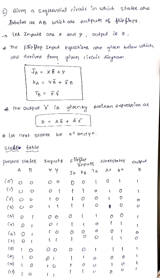
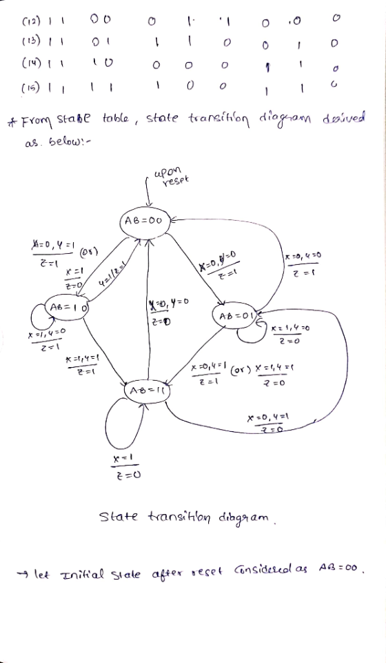
A sequential circuit which is designed using JK Flip-Flops is given below. So, analyse (resolve) the...
 A sequential circuit which is designed using JK Flip-Flops is given below. So, analyse (resolve) the given sequential circuit and draw the corresponding state transition diagram. Also, write down required expressions and determine the sequential circuit model type. Qa should be considered MSB and Z is output. X Qb Ja Qal XI Ka Хаа- Jb Qbi -Z Qa- Kb
The state diagram for a sequential circuit in shown below. Input X, Y Output Z 000,D...
 The state diagram for a sequential circuit in shown below. Input X, Y Output Z 000,D 10/0, 11/0 01/1,11/0 00/0,01/0 01/1,10/1 00/1, 10/0 00/1, 11/1 10/0, 11/1 a) b) c) (4 pts) Find the state table (1 pt) Make a state assignment (3 pts) Find an optimized circuit implementation using SR FFs, NAND gates, and inverters.
9. Given the sequential circuit below, complete its state diagram on the right. Assume the state...
 9. Given the sequential circuit below, complete its state diagram on the right. Assume the state of the top flip flop corresponds to the most significant digit 1 QH CIK
Problem 3: Derive the state diagram and state table for the clocked sequential circuit given below:...
 Problem 3: Derive the state diagram and state table for the clocked sequential circuit given below: X: input Z: output
1. A sequential circuit with two D flip-flops A and B, two inputs, x and y...
1. A sequential circuit with two D flip-flops A and B, two inputs, x and y ; and one output z is specified by the following next-state and output equations A(t + 1) = xy’ + xB B(t + 1) = xA + xB z = A (a) Draw the logic diagram of the circuit. (b) List the state table for the sequential circuit. (c) Draw the corresponding state diagram.
 1. Given the state diagram shown below for a two-state synchronous sequential Mealy circuit with input. and output z, realize the circuit using D flip-flops. Your answer must include the state transition,excita- tion, and output tables, the excitation equation(s), and a labeled circuit diagram 1/0 2. Given the state diagram in Problem 1, realize the circuit using JK flip-flops. Your answer must include the state transition, excitation, and output tables, the excitation equation(s), and a labeled circuit diagram. 3. Given...
 HW#4-SYNCHRONOUS SEQUENTIAL CIRCUIT DESIGN Given the following state diagram, obtain the corresponding synchronous sequential circuit with D flip-flops. Draw this circuit. (Use x as an input, and z as an output). 50 points] 1) 1/0 0/0 1/0
 Thc state transition table bclow is for a sequential circuit with onc input X and onc output Y. The circuit has two state variables A and B, and synchronous input Reset that resets the circuit to state AB-01 when Reset 1: Present State Next State Output X-0 A B A B 0 Reset State 0 0 (9 points) Implement the sequential circuit using minimum number of logic gates and rising- edge triggered D-FFs and draw the logic diagram of the...
 Consider the sequential circuit given below, which has a single input X, a single output Y and two positive edge triggered D flip-flops. a) Write down the logic equations. b) Complete the State Table. c) Draw the State Transition Graph. Logic Equations: Da = Db = Y =
 A sequential circuit which is designed using JK Flip-Flops is given below. So, analyse (resolve) the given sequential circuit and draw the corresponding state transition diagram. Also, write down required expressions and determine the sequential circuit model type. Qa should be considered MSB and Z is output. X Qb Ja Qal XI Ka Хаа- Jb Qbi -Z Qa- Kb
 The state diagram for a sequential circuit in shown below. Input X, Y Output Z 000,D 10/0, 11/0 01/1,11/0 00/0,01/0 01/1,10/1 00/1, 10/0 00/1, 11/1 10/0, 11/1 a) b) c) (4 pts) Find the state table (1 pt) Make a state assignment (3 pts) Find an optimized circuit implementation using SR FFs, NAND gates, and inverters.
 9. Given the sequential circuit below, complete its state diagram on the right. Assume the state of the top flip flop corresponds to the most significant digit 1 QH CIK
 Problem 3: Derive the state diagram and state table for the clocked sequential circuit given below: X: input Z: output
Most questions answered within 3 hours.
-
A crate slides up a frictionless slope. At the end of 3 seconds
its velocity is...
asked 7 minutes ago -
Use the following information to answer the next seven
questions.
Suppose there are three potential states...
asked 3 minutes ago -
If we only have interstitial and substitutional diffusion, then
what do we consider the process of...
asked 19 minutes ago -
You look at yourself in a shiny 9.6-cm-diameter Christmas tree
ball.
If your face is 21.0...
asked 21 minutes ago -
If we were to measure the relaxation time of a muscle after
undergoing tetanus compared to...
asked 20 minutes ago -
4CO(g) + 8H2(g) -----> 3CH4(g) +
CO2(g) + 2H2O(l)
Use the following data as needed to...
asked 23 minutes ago -
without using map
1. Write a C++ program to find out the top 10 words in...
asked 37 minutes ago -
1)Calculate the percent ionization of a
0.330 M solution of hypochlorous
acid.
% Ionization = %...
asked 39 minutes ago -
1a) How many grams of K2SO4 are in 250mL
of 0.11 M K2SO4 solution?
_____ g...
asked 30 minutes ago -
The vapor pressure of a solution containing 38.7 g glycerin
(C3H8O3) in 146.2 g ethanol (C2H5OH)...
asked 35 minutes ago -
A physics major is cooking breakfast when he notices that the
frictional force between the steel...
asked 41 minutes ago -
A cyclohexane (c-hex) solution is prepared by fully dissolving
9.11g of a newly synthesized organic compound...
asked 47 minutes ago