
Homework Answers
Add Answer to:
Building and Testing Circuit:s CIRCUIT 3 Analyse the circuit to determine the expected output voltage Vo for the case shown with C3 10uF. Then repeat the calculations with C3 100uF. Also predict the...
a. Analyse the circuit to determine the expected output voltage Vo for the case shown with C3 10uF. Then repeat the calculations with C3-100uF. Also predict the output voltage V1 for both cases of C3...
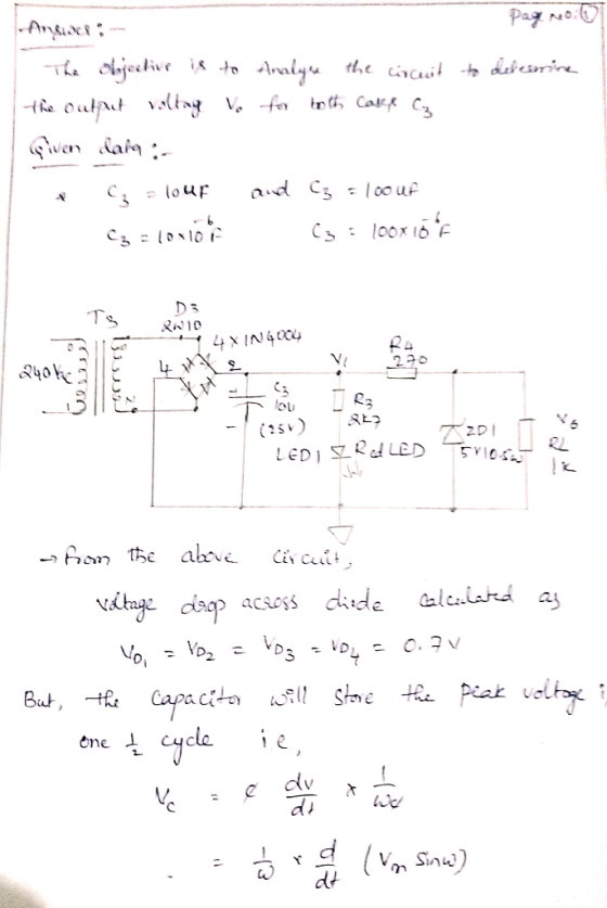
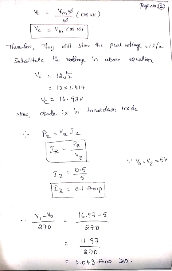
 a. Analyse the circuit to determine the expected output voltage Vo for the case shown with C3 10uF. Then repeat the calculations with C3-100uF. Also predict the output voltage V1 for both cases of C3.1 CIRCUIT 3 Rectifier with Zener Regulator 03 2W10 Ta x 1N4004 240Vac 3I 12Vac C3 Ou (25V) R3 2k7 Vo ZD1 RL 5V1 0.5W k Red LED LED1
a. Analyse the circuit to determine the expected output voltage Vo for the case shown with C3...
a. Analyse the circuit to determine the expected output voltage Vo for the case shown with C3 10uF. Then repeat the calculations with C3-100uF. Also predict the output voltage V1 for both cases of C3.1 CIRCUIT 3 Rectifier with Zener Regulator 03 2W10 Ta x 1N4004 240Vac 3I 12Vac C3 Ou (25V) R3 2k7 Vo ZD1 RL 5V1 0.5W k Red LED LED1
a. Analyse the circuit to determine the expected output voltage Vo for the case shown with C3...
Your supervisor has also passed on to you a power supply circuit sketch to upgrade your last power supply (Assignment 1) so that it has a Fixed 5V regulator output and a Variable Voltage Regulat...
 Your supervisor has also passed on to you a power supply circuit sketch to upgrade your last power supply (Assignment 1) so that it has a Fixed 5V regulator output and a Variable Voltage Regulator output. . Analyse the variable regulator section (containing the LM317 IC) and determine the expected output voltage range the circuit should achieve by the range of adjustment of the 1k potentiometer. Build the circuit and verify the voltage range available. Ensure it can achieve 12V...
 a. Analyse the circuit to determine the expected output voltage Vo for the case shown with C3 10uF. Then repeat the calculations with C3-100uF. Also predict the output voltage V1 for both cases of C3.1 CIRCUIT 3 Rectifier with Zener Regulator 03 2W10 Ta x 1N4004 240Vac 3I 12Vac C3 Ou (25V) R3 2k7 Vo ZD1 RL 5V1 0.5W k Red LED LED1
a. Analyse the circuit to determine the expected output voltage Vo for the case shown with C3...
a. Analyse the circuit to determine the expected output voltage Vo for the case shown with C3 10uF. Then repeat the calculations with C3-100uF. Also predict the output voltage V1 for both cases of C3.1 CIRCUIT 3 Rectifier with Zener Regulator 03 2W10 Ta x 1N4004 240Vac 3I 12Vac C3 Ou (25V) R3 2k7 Vo ZD1 RL 5V1 0.5W k Red LED LED1
a. Analyse the circuit to determine the expected output voltage Vo for the case shown with C3...
 Your supervisor has also passed on to you a power supply circuit sketch to upgrade your last power supply (Assignment 1) so that it has a Fixed 5V regulator output and a Variable Voltage Regulator output. . Analyse the variable regulator section (containing the LM317 IC) and determine the expected output voltage range the circuit should achieve by the range of adjustment of the 1k potentiometer. Build the circuit and verify the voltage range available. Ensure it can achieve 12V...
Most questions answered within 3 hours.
-
A marketing executive who knowingly authorizes a shoddy
defective product to be brought to market is...
asked 2 minutes ago -
Write a psudocode:
1. Define a function called authorize that takes in 2 strings,
uName, and...
asked 7 minutes ago -
What Hall voltage (in mV) is produced by a 0.180 T field applied
across a 2.60...
asked 6 minutes ago -
What mass of ethylene glycol (C2H6O2) must be added to 211.0 g
of water to obtain...
asked 9 minutes ago -
Mary's employer has a defined benefits retirement plan, which
pay 3.2% of her last year's salary...
asked 12 minutes ago -
What are the characteristics and behavior of an ethical
manager?
Explain, in your words, what ethics...
asked 29 minutes ago -
1. Which of the following is NOT an argument that McMahan uses
to show that jus...
asked 50 minutes ago -
A crate slides up a frictionless slope. At the end of 3 seconds
its velocity is...
asked 1 hour ago -
Use the following information to answer the next seven
questions.
Suppose there are three potential states...
asked 1 hour ago -
If we only have interstitial and substitutional diffusion, then
what do we consider the process of...
asked 1 hour ago -
You look at yourself in a shiny 9.6-cm-diameter Christmas tree
ball.
If your face is 21.0...
asked 1 hour ago -
If we were to measure the relaxation time of a muscle after
undergoing tetanus compared to...
asked 1 hour ago