
Homework Answers
Add Answer to:
Thermodynamics A two-stage vapour-compression refrigeration plant shown in Figure Q2 diagrammatically below is discharged with Refrigerant 12. Both compressors are single-acting, single-stage recipro...
Thermodynamics A two-stage vapour-compression refrigeration plant shown in Figure Q2 diagrammatically below is discharged with Refrigerant...
 Thermodynamics
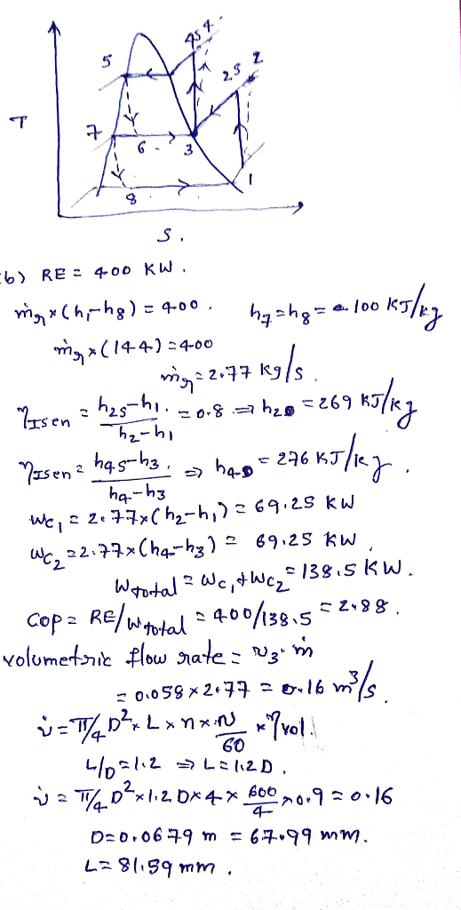
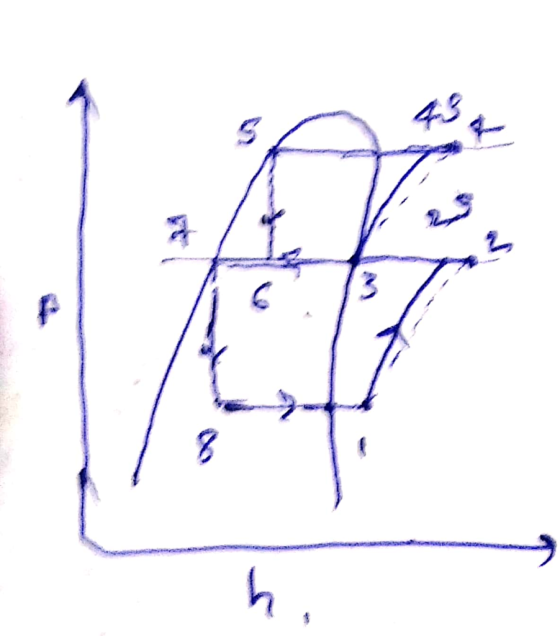
A two-stage vapour-compression refrigeration plant shown in Figure Q2 diagrammatically below is discharged with Refrigerant 12. Both compressors are single-acting, single-stage reciprocating machines with four cylinders and as isentropic efficiency of 80%. They each have a stroke/bore ratio of 1.2 and run at 600 rev/min with a volumetric efficiency of 90%. The condenser, flash chamber and evaporator pressures are 10 bar, 3 bar and 1 bar respectively. Saturation states exist at points 5 and 3 and the vapour at...
Thermodynamics
A two-stage vapour-compression refrigeration plant shown in Figure Q2 diagrammatically below is discharged with Refrigerant 12. Both compressors are single-acting, single-stage reciprocating machines with four cylinders and as isentropic efficiency of 80%. They each have a stroke/bore ratio of 1.2 and run at 600 rev/min with a volumetric efficiency of 90%. The condenser, flash chamber and evaporator pressures are 10 bar, 3 bar and 1 bar respectively. Saturation states exist at points 5 and 3 and the vapour at...
(100 points) Figure below shows the schematic diagram of a two-stage cascade refrigeration system (also called...
 (100 points) Figure below shows the schematic diagram of a two-stage cascade refrigeration system (also called the Economizer 2-Stage Refrigeration Cycle). Comparing to the cascade two-stage refrigeration system discussed in In-class Activity #10a, in this case, the flash chamber (now called Flash Intercooler) is still used but the mixing chamber is removed. The superheated vapor (2) out of the low-pressure compressor (1) is routed into the flash chamber, and the saturated vapor (3) out of the flash chamber enters directly...
The coefficient of performance-of vapor-compression refrigeration cycles
 a) The coefficient of performance-of vapor-compression refrigeration cycles improves when the refrigerant is subcooled before it enters the throttling valve Can the refrigerant be subcooled indefinitely to maximize this effect, or is there a lower limit? Explain brieflyb) A two-stage compression refrigeration system with a flash chamber is used to produce chilled water for a commercial building The refrigeration system operates between a pressure limits of 1 2 MPa and 200 kPa with refrigerant-134a as the working fluid. The refrigerant leaves...
1. MULTI-STAGE COMPRESSION AND EXPANSION The following data refer to a two stage vapour compression system:...
 1. MULTI-STAGE COMPRESSION AND EXPANSION The following data refer to a two stage vapour compression system: Condensing temperature Flash intercooler temperature Evaporating temperature Refrigerant used Refrigerant flow through H.P. side Condensate is sub - cooled in condenser 40 C 15 C -15 C R-717 (NH3) 0.4 kg.s by 5 C 80% each Compression efficiencies Determine the following: (i) Flow rate through evaporator (ii) Tonnes of refrigeration (iii) Total power input (iv) Co-efficient of performance (v) Heat transfer to condenser HPC....
A refrigeration system with a flash chamber operates with R134a between the pressure limits of 1.0 and 0.1 MPa. Th...
 A refrigeration system with a flash chamber operates with R134a between the pressure limits of 1.0 and 0.1 MPa. The refrigerant leaves the condenser as saturated liquid and is throttled to a flash chamber operating at 0.5 MPa. The refrigerant leaving the low-pressure compressor at 0.5 MPa is also routed to the flash chamber. The vapor in the flash chamber is then compressed to the condenser pressure by the high-pressure compressor, and the liquidis throttled to the evaporator pressure. Assume...
A two-stage compression refrigeration system with an adiabatic liquid-vapor separation unit uses refrigerant-134a as working fluid....
A two-stage compression refrigeration system with an adiabatic liquid-vapor separation unit uses refrigerant-134a as working fluid. the system operates the evaporator at 0.4Mpa, the condenser at 1.6Mpa and the separator at 0.8 Mpa. The compressors use 25kW of power. Given that the refrigerant is saturated liquid at the inlet of each compressor, and the compressors are isentropic: i) show the process on a T-s diagram, ii) calculate the rate of cooling provided by the evaporator, the COP of the heat...
A two-stage cascade refrigeration system operates between the pressure limits of 1.4MPa and 200 kPa with...
 A two-stage cascade refrigeration system operates between the pressure limits of 1.4MPa and 200 kPa with refrigerant-134a. The fluid leaves the condenser as a saturated liquid and is throttled to a flash chamber operating at 0.50 MPa. Part of the refrigerant evaporates in the flashing process, and this vapor is mixed with the refrigerant leaving the low-pressurin compressor. The liguid in the flash chamber iS throttled to the evaporator pressure and cools the refrigerated space. The mass flow rate of...
A two-stage compression refrigeration system with an adiabatic liquid-vapor separation unit uses refrigerant-134a as working fluid....
 A two-stage compression refrigeration system with an adiabatic liquid-vapor separation unit uses refrigerant-134a as working fluid. The system operates the evaporator at 0.4 MPa, the condenser at 1.6 MPa, and the separator at 0.8 MPa. The compressors use 25 kW of power. Given that the refrigerant is saturated liquid at the inlet of each expansion valve and saturated vapor at the inlet of each compressor, and the compressors are isentropic: (0) show the process on a T-s diagram; ) calculate...
Thermodynamics. No interpolation needed. Problem #3. Refrigerant 134a is the working fluid for vapor-compression refrigeration cycle....
 Thermodynamics. No interpolation needed.
Problem #3. Refrigerant 134a is the working fluid for vapor-compression refrigeration cycle. The evaporator temperature is 8°C and the condenser pressure is 12 bar. Saturated vapor enters the compressor and superheated vapor enters the condenser at 60°C and exits the condenser as saturated liquid. For a refrigeration capacity of 8 tons or 2.816 x10⁴ J/s determine the following: (1) The refrigerant mass flow rate in kg/s; (2) The compressor isentropic efficiency [Hint: Interpolation is required); (3)...
Thermodynamics. No interpolation needed.
Problem #3. Refrigerant 134a is the working fluid for vapor-compression refrigeration cycle. The evaporator temperature is 8°C and the condenser pressure is 12 bar. Saturated vapor enters the compressor and superheated vapor enters the condenser at 60°C and exits the condenser as saturated liquid. For a refrigeration capacity of 8 tons or 2.816 x10⁴ J/s determine the following: (1) The refrigerant mass flow rate in kg/s; (2) The compressor isentropic efficiency [Hint: Interpolation is required); (3)...
determine 1) sub cooling achieved in the heat exchanger, 2) refrigerant flow rate, 3) cop of the plant ii) A refrigeration unit with 100-ton capacity operates in a vapour compression O refrigerati...
 determine 1) sub cooling achieved in the heat
exchanger, 2) refrigerant flow rate, 3) cop of the plant
ii) A refrigeration unit with 100-ton capacity operates in a vapour compression O refrigeration cycle between the temperature limits of 308 and 263 K. It uses R-12 G as a refrigerantC A heat exchanger is inducted in the circuit in between the condenser and the expander, The refrigerant vapour leaving the evaporator is superheated in the heat exchanger in the countercurrent flow...
determine 1) sub cooling achieved in the heat
exchanger, 2) refrigerant flow rate, 3) cop of the plant
ii) A refrigeration unit with 100-ton capacity operates in a vapour compression O refrigeration cycle between the temperature limits of 308 and 263 K. It uses R-12 G as a refrigerantC A heat exchanger is inducted in the circuit in between the condenser and the expander, The refrigerant vapour leaving the evaporator is superheated in the heat exchanger in the countercurrent flow...
 Thermodynamics
A two-stage vapour-compression refrigeration plant shown in Figure Q2 diagrammatically below is discharged with Refrigerant 12. Both compressors are single-acting, single-stage reciprocating machines with four cylinders and as isentropic efficiency of 80%. They each have a stroke/bore ratio of 1.2 and run at 600 rev/min with a volumetric efficiency of 90%. The condenser, flash chamber and evaporator pressures are 10 bar, 3 bar and 1 bar respectively. Saturation states exist at points 5 and 3 and the vapour at...
Thermodynamics
A two-stage vapour-compression refrigeration plant shown in Figure Q2 diagrammatically below is discharged with Refrigerant 12. Both compressors are single-acting, single-stage reciprocating machines with four cylinders and as isentropic efficiency of 80%. They each have a stroke/bore ratio of 1.2 and run at 600 rev/min with a volumetric efficiency of 90%. The condenser, flash chamber and evaporator pressures are 10 bar, 3 bar and 1 bar respectively. Saturation states exist at points 5 and 3 and the vapour at...
 (100 points) Figure below shows the schematic diagram of a two-stage cascade refrigeration system (also called the Economizer 2-Stage Refrigeration Cycle). Comparing to the cascade two-stage refrigeration system discussed in In-class Activity #10a, in this case, the flash chamber (now called Flash Intercooler) is still used but the mixing chamber is removed. The superheated vapor (2) out of the low-pressure compressor (1) is routed into the flash chamber, and the saturated vapor (3) out of the flash chamber enters directly...
 1. MULTI-STAGE COMPRESSION AND EXPANSION The following data refer to a two stage vapour compression system: Condensing temperature Flash intercooler temperature Evaporating temperature Refrigerant used Refrigerant flow through H.P. side Condensate is sub - cooled in condenser 40 C 15 C -15 C R-717 (NH3) 0.4 kg.s by 5 C 80% each Compression efficiencies Determine the following: (i) Flow rate through evaporator (ii) Tonnes of refrigeration (iii) Total power input (iv) Co-efficient of performance (v) Heat transfer to condenser HPC....
 A refrigeration system with a flash chamber operates with R134a between the pressure limits of 1.0 and 0.1 MPa. The refrigerant leaves the condenser as saturated liquid and is throttled to a flash chamber operating at 0.5 MPa. The refrigerant leaving the low-pressure compressor at 0.5 MPa is also routed to the flash chamber. The vapor in the flash chamber is then compressed to the condenser pressure by the high-pressure compressor, and the liquidis throttled to the evaporator pressure. Assume...
 A two-stage cascade refrigeration system operates between the pressure limits of 1.4MPa and 200 kPa with refrigerant-134a. The fluid leaves the condenser as a saturated liquid and is throttled to a flash chamber operating at 0.50 MPa. Part of the refrigerant evaporates in the flashing process, and this vapor is mixed with the refrigerant leaving the low-pressurin compressor. The liguid in the flash chamber iS throttled to the evaporator pressure and cools the refrigerated space. The mass flow rate of...
 A two-stage compression refrigeration system with an adiabatic liquid-vapor separation unit uses refrigerant-134a as working fluid. The system operates the evaporator at 0.4 MPa, the condenser at 1.6 MPa, and the separator at 0.8 MPa. The compressors use 25 kW of power. Given that the refrigerant is saturated liquid at the inlet of each expansion valve and saturated vapor at the inlet of each compressor, and the compressors are isentropic: (0) show the process on a T-s diagram; ) calculate...
 Thermodynamics. No interpolation needed.
Problem #3. Refrigerant 134a is the working fluid for vapor-compression refrigeration cycle. The evaporator temperature is 8°C and the condenser pressure is 12 bar. Saturated vapor enters the compressor and superheated vapor enters the condenser at 60°C and exits the condenser as saturated liquid. For a refrigeration capacity of 8 tons or 2.816 x10⁴ J/s determine the following: (1) The refrigerant mass flow rate in kg/s; (2) The compressor isentropic efficiency [Hint: Interpolation is required); (3)...
Thermodynamics. No interpolation needed.
Problem #3. Refrigerant 134a is the working fluid for vapor-compression refrigeration cycle. The evaporator temperature is 8°C and the condenser pressure is 12 bar. Saturated vapor enters the compressor and superheated vapor enters the condenser at 60°C and exits the condenser as saturated liquid. For a refrigeration capacity of 8 tons or 2.816 x10⁴ J/s determine the following: (1) The refrigerant mass flow rate in kg/s; (2) The compressor isentropic efficiency [Hint: Interpolation is required); (3)...
 determine 1) sub cooling achieved in the heat
exchanger, 2) refrigerant flow rate, 3) cop of the plant
ii) A refrigeration unit with 100-ton capacity operates in a vapour compression O refrigeration cycle between the temperature limits of 308 and 263 K. It uses R-12 G as a refrigerantC A heat exchanger is inducted in the circuit in between the condenser and the expander, The refrigerant vapour leaving the evaporator is superheated in the heat exchanger in the countercurrent flow...
determine 1) sub cooling achieved in the heat
exchanger, 2) refrigerant flow rate, 3) cop of the plant
ii) A refrigeration unit with 100-ton capacity operates in a vapour compression O refrigeration cycle between the temperature limits of 308 and 263 K. It uses R-12 G as a refrigerantC A heat exchanger is inducted in the circuit in between the condenser and the expander, The refrigerant vapour leaving the evaporator is superheated in the heat exchanger in the countercurrent flow...
Most questions answered within 3 hours.
-
Considering gravitational time dilation, calculate the time that
passes in Earth’s surface while 1 hour passes...
asked 22 minutes ago -
Minitab Problem: Take the Lake Hume June rainfall data and find
use the processes outlined in...
asked 1 hour ago -
X Company is trying to decide whether to continue using old
equipment to make Product A...
asked 1 hour ago -
IN PYTHON ONLY !! Program 2: Re-work
program #5 (WeeklyHours) from the previous assignment such that...
asked 1 hour ago -
The average length of time between arrivals at a turnpike
toll-booth is 26 seconds. What is...
asked 3 hours ago -
(a) A piston at 6.1 atm contains a gas that occupies a volume of
3.5 L....
asked 4 hours ago -
Please answer true or false. Words
cannot be changed or added in to make it true...
asked 4 hours ago -
An empty test tube weighs 15.923 grams. Then,
MgCl2•6H2O is added into the test tube. After...
asked 4 hours ago -
Assume memory access is 10 units of time and disk access is
10000 units of time....
asked 5 hours ago -
1. Are all good samples random?
2. Magazines often report surveys giving statistics such as “63%...
asked 5 hours ago -
Under all the various types of market structures, firms
must eventually earn some economic profits for...
asked 5 hours ago -
Consider the following fitness regime for a single locus trait
with two co-dominant alleles: w11 =...
asked 5 hours ago