

Homework Answers
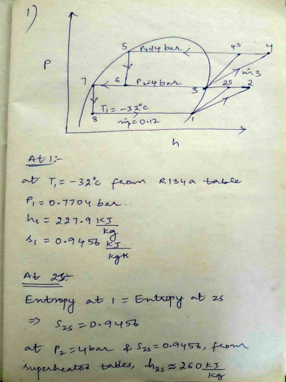
| state | P(bar) | T(celsius) | h(KJ/Kg) | s(KJ/Kg.k) | x | Phase Description |
| 1 | 0.7704 | -32 | 227.9 | 0.9456 | 1 | saturated vapour |
| 2s | 4 | NA | 260 | 0.9456 | NA | superheated vapour |
| 2 | 4 | NA | 264.79 | NA | NA | superheated vapour |
| 3 | 4 | 8.93 | 252.32 | 0.9145 | 1 | saturated vapour |
| 4s | 14 | NA | 278 | 0.9145 | NA | superheated vapour |
| 4 | 14 | NA | 281.837 | NA | NA | superheated vapour |
| 5 | 14 | 52.43 | 125.26 | 0.4453 | 0 | saturated liquid |
| 6 | 4 | 8.93 | 125.26 | 0.464 | 0.3323 | liquid+ vapour mixed region |
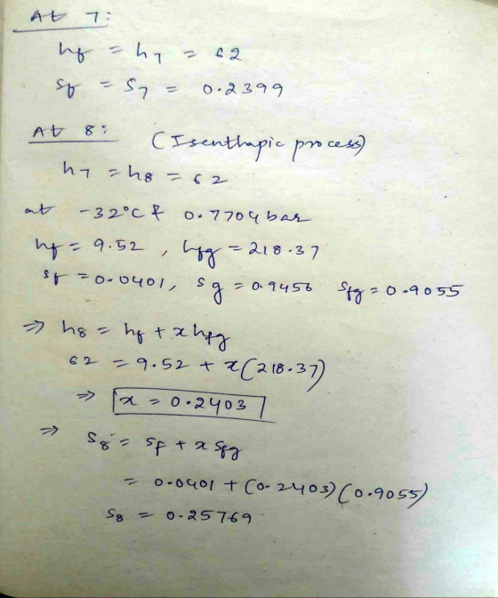
| 7 | 4 | 8.93 | 62 | 0.2399 | 0 | saturated liquid |
| 8 | 0.7704 | -32 | 62 | 0.25769 | 0.2403 | liq+vap mixed region |


Add Answer to:
(100 points) Figure below shows the schematic diagram of a two-stage cascade refrigeration system (also called...
A two-stage cascade refrigeration system operates between the pressure limits of 1.4MPa and 200 kPa with...
 A two-stage cascade refrigeration system operates between the pressure limits of 1.4MPa and 200 kPa with refrigerant-134a. The fluid leaves the condenser as a saturated liquid and is throttled to a flash chamber operating at 0.50 MPa. Part of the refrigerant evaporates in the flashing process, and this vapor is mixed with the refrigerant leaving the low-pressurin compressor. The liguid in the flash chamber iS throttled to the evaporator pressure and cools the refrigerated space. The mass flow rate of...
A refrigeration system with a flash chamber operates with R134a between the pressure limits of 1.0 and 0.1 MPa. Th...
 A refrigeration system with a flash chamber operates with R134a between the pressure limits of 1.0 and 0.1 MPa. The refrigerant leaves the condenser as saturated liquid and is throttled to a flash chamber operating at 0.5 MPa. The refrigerant leaving the low-pressure compressor at 0.5 MPa is also routed to the flash chamber. The vapor in the flash chamber is then compressed to the condenser pressure by the high-pressure compressor, and the liquidis throttled to the evaporator pressure. Assume...
The coefficient of performance-of vapor-compression refrigeration cycles
 a) The coefficient of performance-of vapor-compression refrigeration cycles improves when the refrigerant is subcooled before it enters the throttling valve Can the refrigerant be subcooled indefinitely to maximize this effect, or is there a lower limit? Explain brieflyb) A two-stage compression refrigeration system with a flash chamber is used to produce chilled water for a commercial building The refrigeration system operates between a pressure limits of 1 2 MPa and 200 kPa with refrigerant-134a as the working fluid. The refrigerant leaves...
5-6 Figure 5-6 shows the schematic diagram for a two-stage cascade refrigeration system. Each stage operates...
 5-6 Figure 5-6 shows the schematic diagram for a two-stage cascade refrigeration system. Each stage operates on an ideal vapor-compression refrigeration cycle with refrigerant- 134a as the working fluid. All the important data and refrigerant phases are given in the schematic diagrams. By referring to the diagrams, determine: (a) The ratio of mass flow rate of the system and draw a T-s diagram complete with the data given. Enthalpy values for each states. Compressor power input for Cycle A and...
Part A Consider an ideal two-stage refrigeration system (Figure 1) that uses R-12 as the working...
 Part A Consider an ideal two-stage refrigeration system (Figure 1) that uses R-12 as the working fluid. Saturated liquid leaves the condenser at 40 °C and is throttled to -20 °C. The liquid and vapor at this temperature are separated, and the liquid is throttled to the evaporator temperature at -70 °C. Vapor leaving the evaporator is compressed to the saturation pressure corresponding to -20 °C, after which it is mixed with the vapor leaving the flash chamber. Use TESTCalc...
Problem 2 (30 pts): Consider a two-stage vapor-compression refrigeration system operating between the pressure limits of...
 Problem 2 (30 pts): Consider a two-stage vapor-compression refrigeration system operating between the pressure limits of 1.5 MPa and 150 kPa with refrigerant-134a as the working fluid. The refrigerant leaves the condenser as a saturated liquid and is throttled to a flash chamber operating at 0.45 MPa. The mass flow rate of the refrigerant through the low pressure compressor is 0.15 kg/s. Assuming the refrigerant leaves the evaporator as a saturated vapor, determine (a) the mass flow rate of the...
Pressure limits in a two-stage cooling system are 0.9 MPa and 250kPa. Refrigerant condenser comes out...
 Pressure limits in a two-stage cooling system are 0.9 MPa and
250kPa. Refrigerant condenser
comes out as saturated liquid and works at 700kPa pressure
reduced to the pressure of the evaporation chamber. Meanwhile, some
of the refrigerant evaporates and is mixed with the fluid from the
low pressure compressor. The mixture is then
It is compressed to condenser pressure with high pressure
compressor. The liquid in the evaporation chamber is reduced to
evaporator pressure and draws heat from the cooled...
Pressure limits in a two-stage cooling system are 0.9 MPa and
250kPa. Refrigerant condenser
comes out as saturated liquid and works at 700kPa pressure
reduced to the pressure of the evaporation chamber. Meanwhile, some
of the refrigerant evaporates and is mixed with the fluid from the
low pressure compressor. The mixture is then
It is compressed to condenser pressure with high pressure
compressor. The liquid in the evaporation chamber is reduced to
evaporator pressure and draws heat from the cooled...
5/An ammonia refrigeration system consists of two stages compressors, two cvaporators, flash intereooler and sub-cooler, heat...
 5/An ammonia refrigeration system consists of two stages compressors, two cvaporators, flash intereooler and sub-cooler, heat exchanger and condenser. Ammonia vapor condenses in the condenser at 40 "C. The amount of liquid refrigerant goes to the low temperature evaporator is sub-cooled 10 °C in the liquid sub- cooler and another 10 °C in the liquid-vapor heat exchanger. Vapor leaves the low pressure evaporator saturated at -30 °C, and then it is superheated in the heat exchanger at the same pressure....
-Week 12 6 Help S Required information NOTE: This is a multi-part question. Once an answer is sub...
 -Week 12 6 Help S Required information NOTE: This is a multi-part question. Once an answer is submitted. you wiw be unable to retuwn to this part A two-stage compression refrigeration system operates with refrigerant-134a between the pressure limits of 1.4 MPa and 010 MPa. The refrigerant leaves the condenser as a saturated liquid and is throttled to a flash chamber operating at 0.6 MPa. he flash chamber is maintained at the same pressure as the low pressure discharge which...
A two-stage compression refrigeration system with an adiabatic liquid-vapor separation unit uses refrigerant-134a as working fluid....
 A two-stage compression refrigeration system with an adiabatic liquid-vapor separation unit uses refrigerant-134a as working fluid. The system operates the evaporator at 0.4 MPa, the condenser at 1.6 MPa, and the separator at 0.8 MPa. The compressors use 25 kW of power. Given that the refrigerant is saturated liquid at the inlet of each expansion valve and saturated vapor at the inlet of each compressor, and the compressors are isentropic: (0) show the process on a T-s diagram; ) calculate...
 A two-stage cascade refrigeration system operates between the pressure limits of 1.4MPa and 200 kPa with refrigerant-134a. The fluid leaves the condenser as a saturated liquid and is throttled to a flash chamber operating at 0.50 MPa. Part of the refrigerant evaporates in the flashing process, and this vapor is mixed with the refrigerant leaving the low-pressurin compressor. The liguid in the flash chamber iS throttled to the evaporator pressure and cools the refrigerated space. The mass flow rate of...
 A refrigeration system with a flash chamber operates with R134a between the pressure limits of 1.0 and 0.1 MPa. The refrigerant leaves the condenser as saturated liquid and is throttled to a flash chamber operating at 0.5 MPa. The refrigerant leaving the low-pressure compressor at 0.5 MPa is also routed to the flash chamber. The vapor in the flash chamber is then compressed to the condenser pressure by the high-pressure compressor, and the liquidis throttled to the evaporator pressure. Assume...
 5-6 Figure 5-6 shows the schematic diagram for a two-stage cascade refrigeration system. Each stage operates on an ideal vapor-compression refrigeration cycle with refrigerant- 134a as the working fluid. All the important data and refrigerant phases are given in the schematic diagrams. By referring to the diagrams, determine: (a) The ratio of mass flow rate of the system and draw a T-s diagram complete with the data given. Enthalpy values for each states. Compressor power input for Cycle A and...
 Part A Consider an ideal two-stage refrigeration system (Figure 1) that uses R-12 as the working fluid. Saturated liquid leaves the condenser at 40 °C and is throttled to -20 °C. The liquid and vapor at this temperature are separated, and the liquid is throttled to the evaporator temperature at -70 °C. Vapor leaving the evaporator is compressed to the saturation pressure corresponding to -20 °C, after which it is mixed with the vapor leaving the flash chamber. Use TESTCalc...
 Problem 2 (30 pts): Consider a two-stage vapor-compression refrigeration system operating between the pressure limits of 1.5 MPa and 150 kPa with refrigerant-134a as the working fluid. The refrigerant leaves the condenser as a saturated liquid and is throttled to a flash chamber operating at 0.45 MPa. The mass flow rate of the refrigerant through the low pressure compressor is 0.15 kg/s. Assuming the refrigerant leaves the evaporator as a saturated vapor, determine (a) the mass flow rate of the...
 Pressure limits in a two-stage cooling system are 0.9 MPa and
250kPa. Refrigerant condenser
comes out as saturated liquid and works at 700kPa pressure
reduced to the pressure of the evaporation chamber. Meanwhile, some
of the refrigerant evaporates and is mixed with the fluid from the
low pressure compressor. The mixture is then
It is compressed to condenser pressure with high pressure
compressor. The liquid in the evaporation chamber is reduced to
evaporator pressure and draws heat from the cooled...
Pressure limits in a two-stage cooling system are 0.9 MPa and
250kPa. Refrigerant condenser
comes out as saturated liquid and works at 700kPa pressure
reduced to the pressure of the evaporation chamber. Meanwhile, some
of the refrigerant evaporates and is mixed with the fluid from the
low pressure compressor. The mixture is then
It is compressed to condenser pressure with high pressure
compressor. The liquid in the evaporation chamber is reduced to
evaporator pressure and draws heat from the cooled...
 5/An ammonia refrigeration system consists of two stages compressors, two cvaporators, flash intereooler and sub-cooler, heat exchanger and condenser. Ammonia vapor condenses in the condenser at 40 "C. The amount of liquid refrigerant goes to the low temperature evaporator is sub-cooled 10 °C in the liquid sub- cooler and another 10 °C in the liquid-vapor heat exchanger. Vapor leaves the low pressure evaporator saturated at -30 °C, and then it is superheated in the heat exchanger at the same pressure....
 -Week 12 6 Help S Required information NOTE: This is a multi-part question. Once an answer is submitted. you wiw be unable to retuwn to this part A two-stage compression refrigeration system operates with refrigerant-134a between the pressure limits of 1.4 MPa and 010 MPa. The refrigerant leaves the condenser as a saturated liquid and is throttled to a flash chamber operating at 0.6 MPa. he flash chamber is maintained at the same pressure as the low pressure discharge which...
 A two-stage compression refrigeration system with an adiabatic liquid-vapor separation unit uses refrigerant-134a as working fluid. The system operates the evaporator at 0.4 MPa, the condenser at 1.6 MPa, and the separator at 0.8 MPa. The compressors use 25 kW of power. Given that the refrigerant is saturated liquid at the inlet of each expansion valve and saturated vapor at the inlet of each compressor, and the compressors are isentropic: (0) show the process on a T-s diagram; ) calculate...
Most questions answered within 3 hours.
-
The Problem: The Case of the Harmonizing Vacations
Your CEO is exploring partnering with a European...
asked 1 hour ago -
A chemical equation is balanced by adding coefficients in front
of some formulas so that the...
asked 1 hour ago -
From the literature (reference your sources): What are the
lattice parameters of calcite and aragonite? Why...
asked 2 hours ago -
Your system is rejecting the question am asking which is
preceded by a case study. It...
asked 2 hours ago -
3. On January 2, 2000, Larry creates a trust with himself as
trustee. Larry as trustee...
asked 2 hours ago -
A member of the volleyball team spikes the ball. During this
process, she changes the velocity...
asked 2 hours ago -
Are adult gamers less likely to use a gaming console (Xbox,
PlayStation, Wii, etc...) than teen...
asked 3 hours ago -
The University of
Texas recently reported that 43% of college students aged 18-24
would spend their...
asked 3 hours ago -
The length of stay at a specific emergency department in
Phoenix, Arizona, in 2009 had a...
asked 2 hours ago -
. Please give the mechanism for this type of problem. Step by
Step
The toxin that...
asked 2 hours ago -
If you have a 1M stock solution and you want to dilute 1 :10
with water,...
asked 2 hours ago -
In a load instruction, the effective address is obtained by
A) Retriving the address from a...
asked 2 hours ago