
Homework Answers
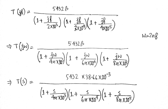
I have use matlab to determine the PM and GM. Following are the matlab commands.
>> s=tf('s')
>> G=(5432*38.66*10^-3)/((1+s/(4*pi*10^3))*(1+s/(6*pi*10^4))*(1+s/(8*pi*10^5)))
G =
1.25e18
------------------------------------------
s^3 + 2.714e06 s^2 + 5.077e11 s + 5.953e15
>> bode(G); margin(G); grid on
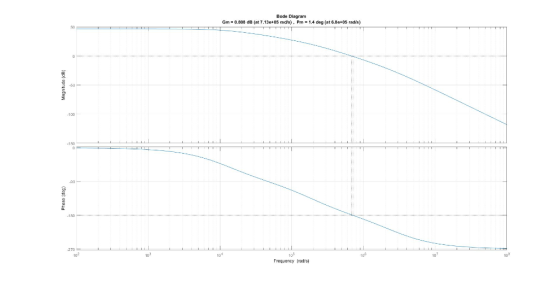
The system is not stable, because Phase Margin is 1.4 degree. To be stable, the system must have Phase margin greater than 45 degree.
NOTE :
a) If you find the solution doubtful or doesn't match with your answer provided, or you feel that I am wrong by any means feel free to mention that in comment. Otherwise your downvote will keep me in doubt. So that i can correct myself and it will also help me in future to guide others.
b) Please re-check the calculation and inform me if there is any error. Happy to help.
c) Some feedbacks or rating will help me to improve myself. Wish you all the best. Happy Learning. Thank You
Add Answer to:
Question 2 (10 marks) Consider the following three-pole feedback amplifier with a loop gain function: 5432xB Tlir)- 2x101+ 4 x 10⁵ If -38.66x10" determine the phase margin and the gain margin...
Question 2 (10 marks) Consider the following three-pole feedback amplifier feedack amplifier with a loop gain func with a loop gain function 5432 T(ir)- 3x10 4x10 If -38.66x10 determine the phase...
 Question 2 (10 marks) Consider the following three-pole feedback amplifier feedack amplifier with a loop gain func with a loop gain function 5432 T(ir)- 3x10 4x10 If -38.66x10 determine the phase margin and the gairn margin of this system (if it is stable)
Question 2 (10 marks) Consider the following three-pole feedback amplifier feedack amplifier with a loop gain func with a loop gain function 5432 T(ir)- 3x10 4x10 If -38.66x10 determine the phase margin and the gairn margin of...
Question 2 (10 marks) Consider the following three-pole feedback amplifier feedack amplifier with a loop gain func with a loop gain function 5432 T(ir)- 3x10 4x10 If -38.66x10 determine the phase margin and the gairn margin of this system (if it is stable)
Question 2 (10 marks) Consider the following three-pole feedback amplifier feedack amplifier with a loop gain func with a loop gain function 5432 T(ir)- 3x10 4x10 If -38.66x10 determine the phase margin and the gairn margin of...
Solve Question 2 The open loop gain of an amplifier is given by 105 Av = 10 105 If the closed loop gain is 100: 1. Show that this amplifier will be stable 2. Calculate the phase margin Questi...
 Solve
Question 2 The open loop gain of an amplifier is given by 105 Av = 10 105 If the closed loop gain is 100: 1. Show that this amplifier will be stable 2. Calculate the phase margin
Question 2 The open loop gain of an amplifier is given by 105 Av = 10 105 If the closed loop gain is 100: 1. Show that this amplifier will be stable 2. Calculate the phase margin
Solve
Question 2 The open loop gain of an amplifier is given by 105 Av = 10 105 If the closed loop gain is 100: 1. Show that this amplifier will be stable 2. Calculate the phase margin
Question 2 The open loop gain of an amplifier is given by 105 Av = 10 105 If the closed loop gain is 100: 1. Show that this amplifier will be stable 2. Calculate the phase margin
Sketch the Bode plots for a stable three-pole amplifier with dc gain 10^5 whose poles have magnit...
 Sketch the Bode plots for a stable three-pole amplifier with dc
gain 10^5 whose poles have magnitudes 0.1 MHz, 1 MHz and 10 MHz.
Find the gain margin and phase margin of the amplifier if it is
connected in a feedback loop with (a) unity feedback factor; (b)
feedback factor 5.623 x 10^-5; (c) closed-loop dc gain 50 dB. In
each case indicate whether the closed-loop amplifier is stable or
unstable. What is the minimum stable closed-loop dc gain of...
Sketch the Bode plots for a stable three-pole amplifier with dc
gain 10^5 whose poles have magnitudes 0.1 MHz, 1 MHz and 10 MHz.
Find the gain margin and phase margin of the amplifier if it is
connected in a feedback loop with (a) unity feedback factor; (b)
feedback factor 5.623 x 10^-5; (c) closed-loop dc gain 50 dB. In
each case indicate whether the closed-loop amplifier is stable or
unstable. What is the minimum stable closed-loop dc gain of...
Question1 Figure 1 represents a shunt-shunt feedback amplifier circuit. The resistors' values and the transistors parameters are also indicated in Figure 1 Voo 8100 Rci 28 KS2 Rci D10 | R.-S...
 Question1 Figure 1 represents a shunt-shunt feedback amplifier circuit. The resistors' values and the transistors parameters are also indicated in Figure 1 Voo 8100 Rci 28 KS2 Rci D10 | R.-S㏀ Hint: in DC analysis; gl -11.538mA/V and 0 R0.2k2 822.85mA/V IE 0.3mA Figure- 1) For R, -10 k2, determine the small-signal closed-loop current-gain A, 2) Determine the small-signal open-loop current-gain.4,- 3) From the results of 2) and 3), determine the loop-gain T Kint: If you did not solve a),...
1:43 You All Media 27/04/2020, 1:41 PM Consider the following three pole feedback amplifier with a...
 1:43 You All Media 27/04/2020, 1:41 PM Consider the following three pole feedback amplifier with a loc faction 200 TO) 1+2x10 +x10 13x109) Determine the phase margin of this system. Is it stable TOSHIBA
A unity gain negative feedback system has an open-loop transfer function given by 4. s) =...
 A unity gain negative feedback system has an open-loop transfer function given by 4. s) = s(1 + 10s)(1 + 10s)? Draw a Bode diagram for this system and determine the loop gain K required for a phase margin of 20 deg. What is the gain margin? 5. We are given the closed-loop transfer function 10(s + 1) T(s) = 82+98+10 for a "unity feedback" system and asked to find the open-loop transfer function, generate a log-magnitude-phase plot for both...
An amplifier is characterised by a 3 pole transfer function of the form where Ao - 100,000, f1( 1...
 An amplifier is characterised by a 3 pole transfer function of the form where Ao - 100,000, f1( 1/2) 1e4 Hz, f2 1e6 Hz, f3 -100e6 Hz By drawing a Bode plot for the amplifier loop gain (or otherwise), determine the phase margin for the amplifier when used with a feedback factor, B-0.5
An amplifier is characterised by a 3 pole transfer function of the form where Ao - 100,000, f1( 1/2) 1e4 Hz, f2 1e6 Hz, f3 -100e6 Hz...
An amplifier is characterised by a 3 pole transfer function of the form where Ao - 100,000, f1( 1/2) 1e4 Hz, f2 1e6 Hz, f3 -100e6 Hz By drawing a Bode plot for the amplifier loop gain (or otherwise), determine the phase margin for the amplifier when used with a feedback factor, B-0.5
An amplifier is characterised by a 3 pole transfer function of the form where Ao - 100,000, f1( 1/2) 1e4 Hz, f2 1e6 Hz, f3 -100e6 Hz...
A unity feedback system has the following open-loop gain function 10 s(s+2) Use MATLAB to plot...
 A unity feedback system has the following open-loop gain function 10 s(s+2) Use MATLAB to plot the Bode plot of this system Find the gain and phase margin. Identify these margins on the Bode plot. Is the G(s) a. b. system stable?
4. (4 Marks) The linear model of a phase detector (phase-lock-loop) can be represented by figure 4. Voltage-controlled oscillator Amplifier Filter LE Figure 4 Phase locked loop The phase-lock systems...
 4. (4 Marks) The linear model of a phase detector (phase-lock-loop) can be represented by figure 4. Voltage-controlled oscillator Amplifier Filter LE Figure 4 Phase locked loop The phase-lock systems are designed to maintain zero difference in phase betweer the input carrier signal and a local voltage controlled oscillator. Phase lock loops find application in colour television, missile tracking and space telemetry. The filter for a particular application is chosen as: 10(s +10) (s +D(s +100) F(s) It is desired...
6) Consider the feedback system in Figure 1 with the loop transfer function a) [8 Marks]...
 6) Consider the feedback system in Figure 1 with the loop transfer function a) [8 Marks] Plot the Bode diagram for this loop transfer function b) 10 Marks] Determine the frequency at which the gain has unit magnitude and compute the phase angle at that frequency. Controller Process G(s)Y(s) Figure 1
 Question 2 (10 marks) Consider the following three-pole feedback amplifier feedack amplifier with a loop gain func with a loop gain function 5432 T(ir)- 3x10 4x10 If -38.66x10 determine the phase margin and the gairn margin of this system (if it is stable)
Question 2 (10 marks) Consider the following three-pole feedback amplifier feedack amplifier with a loop gain func with a loop gain function 5432 T(ir)- 3x10 4x10 If -38.66x10 determine the phase margin and the gairn margin of...
Question 2 (10 marks) Consider the following three-pole feedback amplifier feedack amplifier with a loop gain func with a loop gain function 5432 T(ir)- 3x10 4x10 If -38.66x10 determine the phase margin and the gairn margin of this system (if it is stable)
Question 2 (10 marks) Consider the following three-pole feedback amplifier feedack amplifier with a loop gain func with a loop gain function 5432 T(ir)- 3x10 4x10 If -38.66x10 determine the phase margin and the gairn margin of...
 Solve
Question 2 The open loop gain of an amplifier is given by 105 Av = 10 105 If the closed loop gain is 100: 1. Show that this amplifier will be stable 2. Calculate the phase margin
Question 2 The open loop gain of an amplifier is given by 105 Av = 10 105 If the closed loop gain is 100: 1. Show that this amplifier will be stable 2. Calculate the phase margin
Solve
Question 2 The open loop gain of an amplifier is given by 105 Av = 10 105 If the closed loop gain is 100: 1. Show that this amplifier will be stable 2. Calculate the phase margin
Question 2 The open loop gain of an amplifier is given by 105 Av = 10 105 If the closed loop gain is 100: 1. Show that this amplifier will be stable 2. Calculate the phase margin
 Sketch the Bode plots for a stable three-pole amplifier with dc
gain 10^5 whose poles have magnitudes 0.1 MHz, 1 MHz and 10 MHz.
Find the gain margin and phase margin of the amplifier if it is
connected in a feedback loop with (a) unity feedback factor; (b)
feedback factor 5.623 x 10^-5; (c) closed-loop dc gain 50 dB. In
each case indicate whether the closed-loop amplifier is stable or
unstable. What is the minimum stable closed-loop dc gain of...
Sketch the Bode plots for a stable three-pole amplifier with dc
gain 10^5 whose poles have magnitudes 0.1 MHz, 1 MHz and 10 MHz.
Find the gain margin and phase margin of the amplifier if it is
connected in a feedback loop with (a) unity feedback factor; (b)
feedback factor 5.623 x 10^-5; (c) closed-loop dc gain 50 dB. In
each case indicate whether the closed-loop amplifier is stable or
unstable. What is the minimum stable closed-loop dc gain of...
 Question1 Figure 1 represents a shunt-shunt feedback amplifier circuit. The resistors' values and the transistors parameters are also indicated in Figure 1 Voo 8100 Rci 28 KS2 Rci D10 | R.-S㏀ Hint: in DC analysis; gl -11.538mA/V and 0 R0.2k2 822.85mA/V IE 0.3mA Figure- 1) For R, -10 k2, determine the small-signal closed-loop current-gain A, 2) Determine the small-signal open-loop current-gain.4,- 3) From the results of 2) and 3), determine the loop-gain T Kint: If you did not solve a),...
 1:43 You All Media 27/04/2020, 1:41 PM Consider the following three pole feedback amplifier with a loc faction 200 TO) 1+2x10 +x10 13x109) Determine the phase margin of this system. Is it stable TOSHIBA
 A unity gain negative feedback system has an open-loop transfer function given by 4. s) = s(1 + 10s)(1 + 10s)? Draw a Bode diagram for this system and determine the loop gain K required for a phase margin of 20 deg. What is the gain margin? 5. We are given the closed-loop transfer function 10(s + 1) T(s) = 82+98+10 for a "unity feedback" system and asked to find the open-loop transfer function, generate a log-magnitude-phase plot for both...
 An amplifier is characterised by a 3 pole transfer function of the form where Ao - 100,000, f1( 1/2) 1e4 Hz, f2 1e6 Hz, f3 -100e6 Hz By drawing a Bode plot for the amplifier loop gain (or otherwise), determine the phase margin for the amplifier when used with a feedback factor, B-0.5
An amplifier is characterised by a 3 pole transfer function of the form where Ao - 100,000, f1( 1/2) 1e4 Hz, f2 1e6 Hz, f3 -100e6 Hz...
An amplifier is characterised by a 3 pole transfer function of the form where Ao - 100,000, f1( 1/2) 1e4 Hz, f2 1e6 Hz, f3 -100e6 Hz By drawing a Bode plot for the amplifier loop gain (or otherwise), determine the phase margin for the amplifier when used with a feedback factor, B-0.5
An amplifier is characterised by a 3 pole transfer function of the form where Ao - 100,000, f1( 1/2) 1e4 Hz, f2 1e6 Hz, f3 -100e6 Hz...
 A unity feedback system has the following open-loop gain function 10 s(s+2) Use MATLAB to plot the Bode plot of this system Find the gain and phase margin. Identify these margins on the Bode plot. Is the G(s) a. b. system stable?
 4. (4 Marks) The linear model of a phase detector (phase-lock-loop) can be represented by figure 4. Voltage-controlled oscillator Amplifier Filter LE Figure 4 Phase locked loop The phase-lock systems are designed to maintain zero difference in phase betweer the input carrier signal and a local voltage controlled oscillator. Phase lock loops find application in colour television, missile tracking and space telemetry. The filter for a particular application is chosen as: 10(s +10) (s +D(s +100) F(s) It is desired...
 6) Consider the feedback system in Figure 1 with the loop transfer function a) [8 Marks] Plot the Bode diagram for this loop transfer function b) 10 Marks] Determine the frequency at which the gain has unit magnitude and compute the phase angle at that frequency. Controller Process G(s)Y(s) Figure 1
Most questions answered within 3 hours.
-
. For this set of questions, determine what
proportion of a normal distribution is located betweeneach...
asked 19 minutes ago -
A college student is employed as a door-to-door newspaper
salesman. Historical data suggests that the student...
asked 1 hour ago -
MATLAB HW 11 problem using Switch Case and Input commands
Write a script file that calculates...
asked 58 minutes ago -
Considering gravitational time dilation, calculate the time that
passes in Earth’s surface while 1 hour passes...
asked 1 hour ago -
Minitab Problem: Take the Lake Hume June rainfall data and find
use the processes outlined in...
asked 2 hours ago -
X Company is trying to decide whether to continue using old
equipment to make Product A...
asked 2 hours ago -
IN PYTHON ONLY !! Program 2: Re-work
program #5 (WeeklyHours) from the previous assignment such that...
asked 3 hours ago -
The average length of time between arrivals at a turnpike
toll-booth is 26 seconds. What is...
asked 4 hours ago -
(a) A piston at 6.1 atm contains a gas that occupies a volume of
3.5 L....
asked 5 hours ago -
Please answer true or false. Words
cannot be changed or added in to make it true...
asked 5 hours ago -
An empty test tube weighs 15.923 grams. Then,
MgCl2•6H2O is added into the test tube. After...
asked 5 hours ago -
Assume memory access is 10 units of time and disk access is
10000 units of time....
asked 6 hours ago