
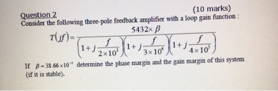
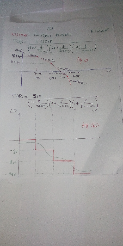
Question 2 Consider the following three-pole feedback amplifier with a loop gain function (10 marks) 5432× β 3 x 10 2x10³ 4x 10 If B-38.66x10 determine the phase margin and the gain margin of this system (if it is stable)
Homework Answers

Add Answer to:
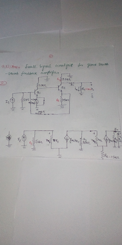
Question1 Figure 1 represents a shunt-shunt feedback amplifier circuit. The resistors' values and the transistors parameters are also indicated in Figure 1 Voo 8100 Rci 28 KS2 Rci D10 | R.-S...
Question 1 (10 marks) Figure 10 Rc2 shunt-shunt28R feedback amplifier circuit The resistors values and the transistors parameters are also indicated in Figure 1 1,-0.3mA 285m Hint: in DC analysis...
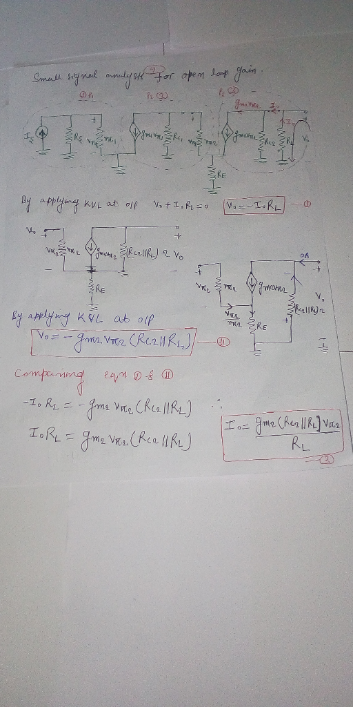
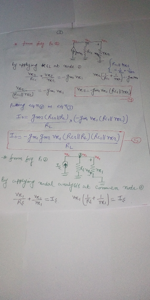
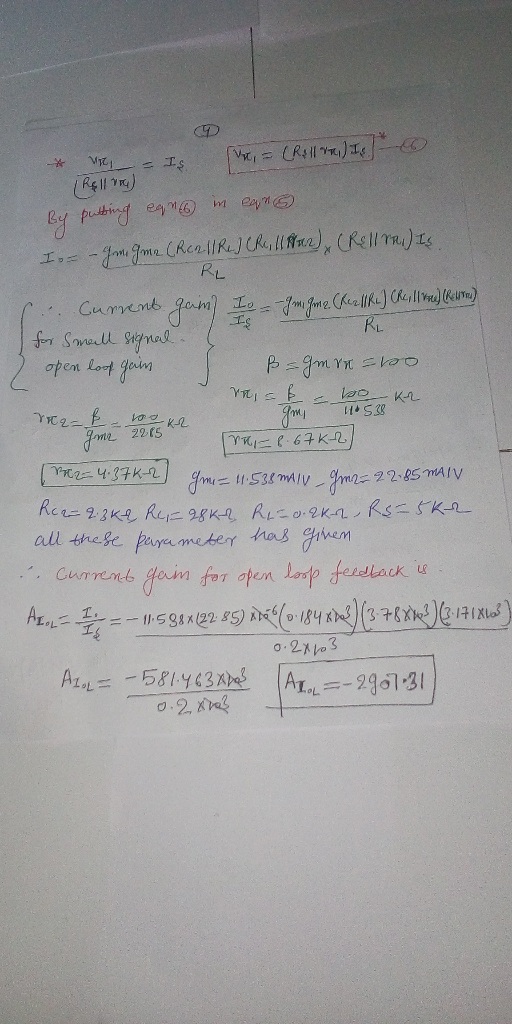
 Question 1 (10 marks) Figure 10 Rc2 shunt-shunt28R feedback amplifier circuit The resistors values and the transistors parameters are also indicated in Figure 1 1,-0.3mA 285m Hint: in DC analysis; 1) For R,-104, determine the small-signal closed-loop current-gain'. 2) Determine the small-signal open-loop current-gain 3) From the results of 2) and 3), determine the loop-gain T: Hint: If you did not solve 2), assume If you did not solve 3), assume600
Question 1 (10 marks) Figure 10 Rc2 shunt-shunt28R feedback...
Question 1 (10 marks) Figure 10 Rc2 shunt-shunt28R feedback amplifier circuit The resistors values and the transistors parameters are also indicated in Figure 1 1,-0.3mA 285m Hint: in DC analysis; 1) For R,-104, determine the small-signal closed-loop current-gain'. 2) Determine the small-signal open-loop current-gain 3) From the results of 2) and 3), determine the loop-gain T: Hint: If you did not solve 2), assume If you did not solve 3), assume600
Question 1 (10 marks) Figure 10 Rc2 shunt-shunt28R feedback...
Question 4: Figure 4 In the series-shunt feedback amplifier shown in Figure 4, the transistors are...
 Question 4: Figure 4 In the series-shunt feedback amplifier shown in Figure 4, the transistors are biased with ideal current-sources 1, 0.1mA, 12 1mA, the devices operate with VE0.7V and t = 100. The input signal V, has a zero DC component. Resistances are (a) If the open loop gain is large, what do you expect the closed-loop gain A, -V/V, to be? Give both an expression and its approximate value (b) Find the DC emitter current in each of...
pleaseee solve quickly it s urgent!!!!! EEN 311-Electronic Circuits ll (3 eredíįs)-Final Exam fferential amplifier biased with a basic current source rollowing parameters: Voo-Va 12 V. RD 8 ka, a...
 pleaseee solve quickly it s urgent!!!!!
EEN 311-Electronic Circuits ll (3 eredíįs)-Final Exam fferential amplifier biased with a basic current source rollowing parameters: Voo-Va 12 V. RD 8 ka, and 5. (20 points) Consider the di The circuit has the param Vi - 650 mv, Vov 50 mV, and R 10 k2. The transistors are matched and have: Va=80 V 几 Von Ro &K 오, DGI + VDD REF Q4 THE DE CEER Vss Determine: a) the reference current IREF...
pleaseee solve quickly it s urgent!!!!!
EEN 311-Electronic Circuits ll (3 eredíįs)-Final Exam fferential amplifier biased with a basic current source rollowing parameters: Voo-Va 12 V. RD 8 ka, and 5. (20 points) Consider the di The circuit has the param Vi - 650 mv, Vov 50 mV, and R 10 k2. The transistors are matched and have: Va=80 V 几 Von Ro &K 오, DGI + VDD REF Q4 THE DE CEER Vss Determine: a) the reference current IREF...
Q1. The values of the difference amplifier in figure 1 are Ao 5x 10⁵, Rı =...
 Q1. The values of the difference amplifier in figure 1 are Ao 5x 10⁵, Rı = 5kQ, RF = 50M, Ra-2kQ, and Rx-20kS2. The input voltages are vb-5mV and Va--15mV. Find the out voltage vo. (5 Points) RF R1 Figure 1 Q2. Design an integrator as shown in figure 2 to be operated with an AC signal of 5 kHz and to give a closed loop voltage gain of Af-10 at w=1 rad/s. (5 Points) iRF RI 79 +Vcc 2...
Laboratory 1: operation amplifier characteristics A. Objectives: 1. To study the basic characteri...
 thanks
Laboratory 1: operation amplifier characteristics A. Objectives: 1. To study the basic characteristics of an operational amplifier 2. To study the bias circuit of an operational amplifier B. Apparatus: 1. DC Power supply 2. Experimental board and corresponding components 3. Electronic calculator (prepared by students) 4. Digital camera (prepared by students for photo taking of the experimental results) 5. Laptop computer with the software PicoScope 6 and Microsoft Word installed. 6. PicoScope PC Oscilloscope and its accessories. 7. Multimeter...
thanks
Laboratory 1: operation amplifier characteristics A. Objectives: 1. To study the basic characteristics of an operational amplifier 2. To study the bias circuit of an operational amplifier B. Apparatus: 1. DC Power supply 2. Experimental board and corresponding components 3. Electronic calculator (prepared by students) 4. Digital camera (prepared by students for photo taking of the experimental results) 5. Laptop computer with the software PicoScope 6 and Microsoft Word installed. 6. PicoScope PC Oscilloscope and its accessories. 7. Multimeter...
Yes, this is one problem. Please solve ALL PARTS. Guaranteed thumbs up for the person who solves it. 3 1. Photodiode...
 Yes, this is one problem. Please solve ALL PARTS. Guaranteed
thumbs up for the person who solves it.
3 1. Photodiode amplifier circuit You are designinga CF photosensor circuit for a light detection and ranging LiDAR) system in autonomous vehicles. The circuit utilizes a transimpedance amplifier to convert low-level RF photodiode current signal to a usable voltage output. It consists of a photodiode, an amplifier, and feedback capacitor/resistor pair as shown in Figure 1. We will derive simple equations to...
Yes, this is one problem. Please solve ALL PARTS. Guaranteed
thumbs up for the person who solves it.
3 1. Photodiode amplifier circuit You are designinga CF photosensor circuit for a light detection and ranging LiDAR) system in autonomous vehicles. The circuit utilizes a transimpedance amplifier to convert low-level RF photodiode current signal to a usable voltage output. It consists of a photodiode, an amplifier, and feedback capacitor/resistor pair as shown in Figure 1. We will derive simple equations to...
 Question 1 (10 marks) Figure 10 Rc2 shunt-shunt28R feedback amplifier circuit The resistors values and the transistors parameters are also indicated in Figure 1 1,-0.3mA 285m Hint: in DC analysis; 1) For R,-104, determine the small-signal closed-loop current-gain'. 2) Determine the small-signal open-loop current-gain 3) From the results of 2) and 3), determine the loop-gain T: Hint: If you did not solve 2), assume If you did not solve 3), assume600
Question 1 (10 marks) Figure 10 Rc2 shunt-shunt28R feedback...
Question 1 (10 marks) Figure 10 Rc2 shunt-shunt28R feedback amplifier circuit The resistors values and the transistors parameters are also indicated in Figure 1 1,-0.3mA 285m Hint: in DC analysis; 1) For R,-104, determine the small-signal closed-loop current-gain'. 2) Determine the small-signal open-loop current-gain 3) From the results of 2) and 3), determine the loop-gain T: Hint: If you did not solve 2), assume If you did not solve 3), assume600
Question 1 (10 marks) Figure 10 Rc2 shunt-shunt28R feedback...
 Question 4: Figure 4 In the series-shunt feedback amplifier shown in Figure 4, the transistors are biased with ideal current-sources 1, 0.1mA, 12 1mA, the devices operate with VE0.7V and t = 100. The input signal V, has a zero DC component. Resistances are (a) If the open loop gain is large, what do you expect the closed-loop gain A, -V/V, to be? Give both an expression and its approximate value (b) Find the DC emitter current in each of...
 pleaseee solve quickly it s urgent!!!!!
EEN 311-Electronic Circuits ll (3 eredíįs)-Final Exam fferential amplifier biased with a basic current source rollowing parameters: Voo-Va 12 V. RD 8 ka, and 5. (20 points) Consider the di The circuit has the param Vi - 650 mv, Vov 50 mV, and R 10 k2. The transistors are matched and have: Va=80 V 几 Von Ro &K 오, DGI + VDD REF Q4 THE DE CEER Vss Determine: a) the reference current IREF...
pleaseee solve quickly it s urgent!!!!!
EEN 311-Electronic Circuits ll (3 eredíįs)-Final Exam fferential amplifier biased with a basic current source rollowing parameters: Voo-Va 12 V. RD 8 ka, and 5. (20 points) Consider the di The circuit has the param Vi - 650 mv, Vov 50 mV, and R 10 k2. The transistors are matched and have: Va=80 V 几 Von Ro &K 오, DGI + VDD REF Q4 THE DE CEER Vss Determine: a) the reference current IREF...
 Q1. The values of the difference amplifier in figure 1 are Ao 5x 10⁵, Rı = 5kQ, RF = 50M, Ra-2kQ, and Rx-20kS2. The input voltages are vb-5mV and Va--15mV. Find the out voltage vo. (5 Points) RF R1 Figure 1 Q2. Design an integrator as shown in figure 2 to be operated with an AC signal of 5 kHz and to give a closed loop voltage gain of Af-10 at w=1 rad/s. (5 Points) iRF RI 79 +Vcc 2...
 thanks
Laboratory 1: operation amplifier characteristics A. Objectives: 1. To study the basic characteristics of an operational amplifier 2. To study the bias circuit of an operational amplifier B. Apparatus: 1. DC Power supply 2. Experimental board and corresponding components 3. Electronic calculator (prepared by students) 4. Digital camera (prepared by students for photo taking of the experimental results) 5. Laptop computer with the software PicoScope 6 and Microsoft Word installed. 6. PicoScope PC Oscilloscope and its accessories. 7. Multimeter...
thanks
Laboratory 1: operation amplifier characteristics A. Objectives: 1. To study the basic characteristics of an operational amplifier 2. To study the bias circuit of an operational amplifier B. Apparatus: 1. DC Power supply 2. Experimental board and corresponding components 3. Electronic calculator (prepared by students) 4. Digital camera (prepared by students for photo taking of the experimental results) 5. Laptop computer with the software PicoScope 6 and Microsoft Word installed. 6. PicoScope PC Oscilloscope and its accessories. 7. Multimeter...
 Yes, this is one problem. Please solve ALL PARTS. Guaranteed
thumbs up for the person who solves it.
3 1. Photodiode amplifier circuit You are designinga CF photosensor circuit for a light detection and ranging LiDAR) system in autonomous vehicles. The circuit utilizes a transimpedance amplifier to convert low-level RF photodiode current signal to a usable voltage output. It consists of a photodiode, an amplifier, and feedback capacitor/resistor pair as shown in Figure 1. We will derive simple equations to...
Yes, this is one problem. Please solve ALL PARTS. Guaranteed
thumbs up for the person who solves it.
3 1. Photodiode amplifier circuit You are designinga CF photosensor circuit for a light detection and ranging LiDAR) system in autonomous vehicles. The circuit utilizes a transimpedance amplifier to convert low-level RF photodiode current signal to a usable voltage output. It consists of a photodiode, an amplifier, and feedback capacitor/resistor pair as shown in Figure 1. We will derive simple equations to...
Most questions answered within 3 hours.
-
What are the negative effects of abruptly stopping the use of
all fossil fuels? Give at...
asked 6 minutes ago -
Given that many conflict are the result of different parties having
different interests, is it possible...
asked 11 minutes ago -
A 750 g block can slide uniformly along the horizontal track
when a string attached to...
asked 14 minutes ago -
In 2017, Juan entered into a contract to write a book. The
publisher advanced Juan $50,000,...
asked 28 minutes ago -
Determine the number of kinds of protons in each molecule (w/
respect to NMR spectroscopy). Drawing...
asked 38 minutes ago -
A jeweler whose near point is 68 cm from his eye uses a
magnifying glass as...
asked 36 minutes ago -
A company wants to determine how many units of each of two
products, A and B,...
asked 40 minutes ago -
The blood pressure of a person changes throughout the day.
Suppose the systolic blood pressure of...
asked 49 minutes ago -
A chemistry student desired to study sulfur. Sulfur exhibited
the following characteristics with oxygen:
(a) It...
asked 45 minutes ago -
An Atwood machine is constructed of a solid-disk frictionless
pulley of mass m3 and radius R....
asked 46 minutes ago -
what are the advantages of lanthanum hexaboride over tungsten
filament for electron emission
what is the...
asked 48 minutes ago -
Question 5
Your uncle offers to sell you his vintage Rolls Royce. He
suggests a payment...
asked 53 minutes ago