
Homework Answers
Add Answer to:
Control System 3) Consider the simplified form of the transfer function for position servomechanism used in an antenna tracking system as shown in Figure Q3. By using root locus technique: Error Els)...
Sketch the root locus for the control system shown in Figure Q3(b). b) Calculate the breakaway...
 Sketch the root locus for the control system shown in Figure Q3(b). b) Calculate the breakaway value of K and its location. Comment on the stability of the system. 1 G(s) and Ge(s) K (s+ 1) (s+2) where K is a positive constant C(s) R(s) G(s) Ge(s) Figure Q3(b) If the control system is modified by an addition of an open loop pole at s - 6 ii) 1 sketch the new root locus showing such that G(s) (s+1) (s+2)(s...
Q3. Consider the feedback system in Figure 3. In the case when 2L G(s) Figure 3:...
 Q3. Consider the feedback system in Figure 3. In the case when 2L G(s) Figure 3: Block diagranm G(s) and when k is positive: (a) Sketch the root locus of the closed loop system (10) To assist in this (to indicate on root locus diagram) ) Compute the open loop poles and zeros (i) ealeulate the portion of the locus lying on the real axis; (iii) calculate the angles of asymptotes make with the real axis arad also the value...
[7] Sketch the root locus for the unity feedback system whose open loop transfer function is K G(s) Draw the root locus...
 [7] Sketch the root locus for the unity feedback system whose open loop transfer function is K G(s) Draw the root locus of the system with the gain K as a variable s(s+4) (s2+4s+20)' Determine asymptotes, centroid,, breakaway point, angle of departure, and the gain at which root locus crosses jw -axis.
[7] Sketch the root locus for the unity feedback system whose open loop transfer function is K G(s) Draw the root locus of the system with the gain...
[7] Sketch the root locus for the unity feedback system whose open loop transfer function is K G(s) Draw the root locus of the system with the gain K as a variable s(s+4) (s2+4s+20)' Determine asymptotes, centroid,, breakaway point, angle of departure, and the gain at which root locus crosses jw -axis.
[7] Sketch the root locus for the unity feedback system whose open loop transfer function is K G(s) Draw the root locus of the system with the gain...
Can you Solve in matlab please. I need your help B-7-6. Consider the system shown in Figure 7-59. Plot the root loci for the system. Determine the value of K such that the damping ratio ζ of the d...
 Can you Solve in matlab please. I need your help
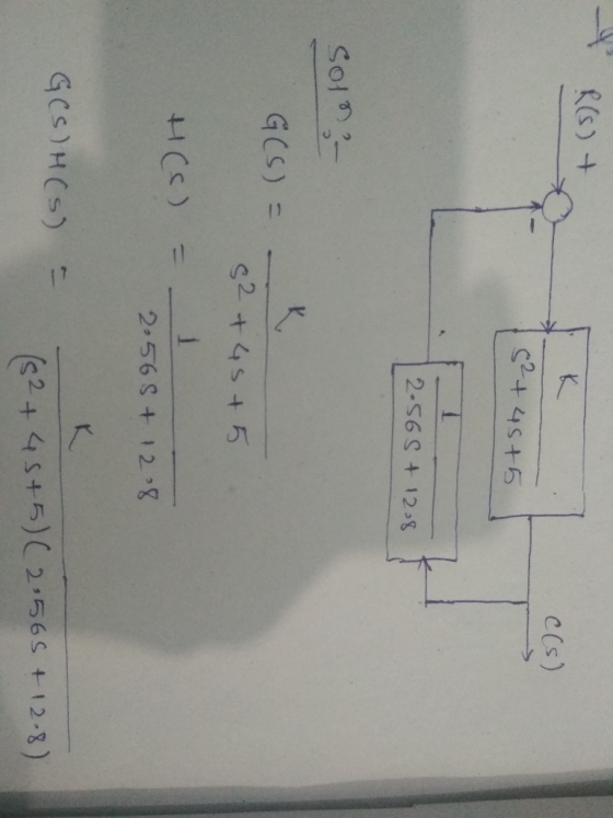
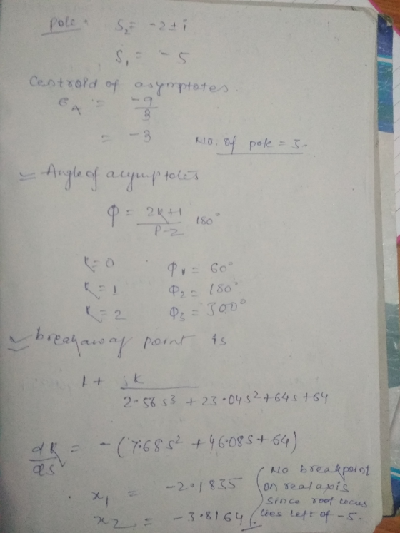
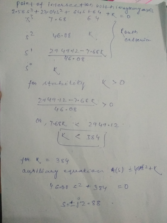
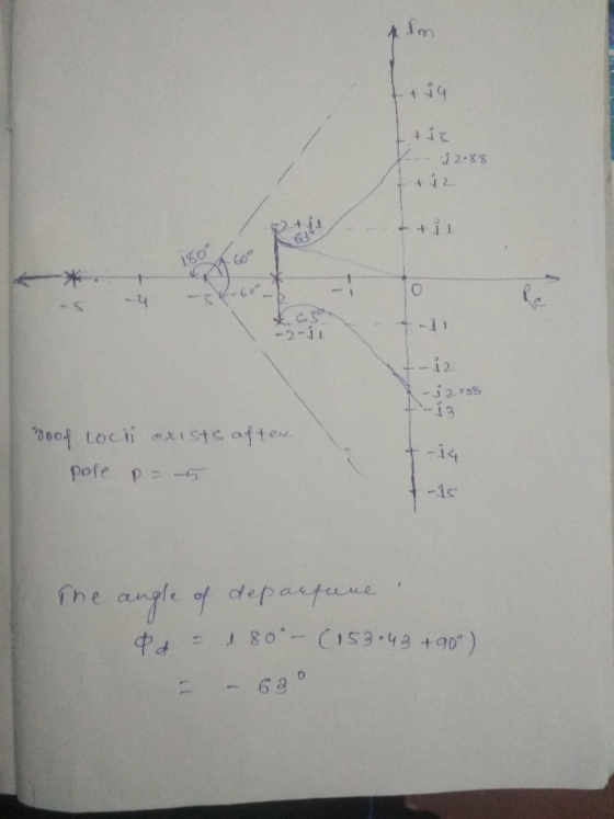
B-7-6. Consider the system shown in Figure 7-59. Plot the root loci for the system. Determine the value of K such that the damping ratio ζ of the dominant closed-loop poles is 05. Then determine all closed-loop poles. Plot the unit-step response curve with MATLAB. s(s2 +4s +5) Figure 7-59 Control system.
B-7-6. Consider the system shown in Figure 7-59. Plot the root loci for the system. Determine the value...
Can you Solve in matlab please. I need your help
B-7-6. Consider the system shown in Figure 7-59. Plot the root loci for the system. Determine the value of K such that the damping ratio ζ of the dominant closed-loop poles is 05. Then determine all closed-loop poles. Plot the unit-step response curve with MATLAB. s(s2 +4s +5) Figure 7-59 Control system.
B-7-6. Consider the system shown in Figure 7-59. Plot the root loci for the system. Determine the value...
Sketch the root locus plot of a unity feedback system with an open loop transfer function...
Sketch the root locus plot of a unity feedback system with an open loop transfer function G(s) = K / s (s+2) (s+4) Determine the value of K so that the dominant pair of complex poles of the system has a damping ratio of 0.5.
3. Consider the system shown below. For this system. G(s) s(s+1)(s 2) H(s)1 We assume that the value of the gain K is nonnegative. Sketch the root locus plot and determine the K value such that the d...
 3. Consider the system shown below. For this system. G(s) s(s+1)(s 2) H(s)1 We assume that the value of the gain K is nonnegative. Sketch the root locus plot and determine the K value such that the damping ratio of a pair of dominant complex-conjugate closed-loop poles is 0.5. Ri)1 C(s)
3. Consider the system shown below. For this system. G(s) s(s+1)(s 2) H(s)1 We assume that the value of the gain K is nonnegative. Sketch the root locus plot...
3. Consider the system shown below. For this system. G(s) s(s+1)(s 2) H(s)1 We assume that the value of the gain K is nonnegative. Sketch the root locus plot and determine the K value such that the damping ratio of a pair of dominant complex-conjugate closed-loop poles is 0.5. Ri)1 C(s)
3. Consider the system shown below. For this system. G(s) s(s+1)(s 2) H(s)1 We assume that the value of the gain K is nonnegative. Sketch the root locus plot...
Problem (4): Sketch the root locus plot for a system, whose transfer function are given by 10 K (s2 +3 s+7) the complex poles. G(s) (s +3) i) Determine the joo -axis crossing, breakaway point and the...
 Problem (4): Sketch the root locus plot for a system, whose transfer function are given by 10 K (s2 +3 s+7) the complex poles. G(s) (s +3) i) Determine the joo -axis crossing, breakaway point and the angle of departure from (i) Determine the value of the gain for which the closed loop system will have a pole at (-10)
Problem (4): Sketch the root locus plot for a system, whose transfer function are given by 10 K (s2 +3...
Problem (4): Sketch the root locus plot for a system, whose transfer function are given by 10 K (s2 +3 s+7) the complex poles. G(s) (s +3) i) Determine the joo -axis crossing, breakaway point and the angle of departure from (i) Determine the value of the gain for which the closed loop system will have a pole at (-10)
Problem (4): Sketch the root locus plot for a system, whose transfer function are given by 10 K (s2 +3...
Q. 1 (5 marks) For the system in Fig. (a). Assume proportion control, Gc(s)-K, sketch the root lo...
 pls answer dont just copy other solution or ur catching a
dislike
Q. 1 (5 marks) For the system in Fig. (a). Assume proportion control, Gc(s)-K, sketch the root locus for the closed-loop system (b). Using the angle condition, prove that s12 +j2 is not on the root locus. (c). Design a lead compensator Ge(s) - K such that the dominant closed-loop poles are located at s1--2 2. (d), What are the zero and pole of lead compensator G() (e)....
pls answer dont just copy other solution or ur catching a
dislike
Q. 1 (5 marks) For the system in Fig. (a). Assume proportion control, Gc(s)-K, sketch the root locus for the closed-loop system (b). Using the angle condition, prove that s12 +j2 is not on the root locus. (c). Design a lead compensator Ge(s) - K such that the dominant closed-loop poles are located at s1--2 2. (d), What are the zero and pole of lead compensator G() (e)....
A robot force control system with unity feedback has a loop transfer function [6 7.11 Tood transf...
 A robot force control system with unity feedback has a loop transfer function [6 7.11 Tood transfer function (6l K(s +2.5) (s2 + 2s 2) (s2 + 4s + 5) (a) Find the gain K that results in dominant roots with a damping ratio of 0.707. Sketch the root locus. (b) Find the actual percent overshoot and peak time for the gain K of part (a)
A robot force control system with unity feedback has a loop transfer function [6...
A robot force control system with unity feedback has a loop transfer function [6 7.11 Tood transfer function (6l K(s +2.5) (s2 + 2s 2) (s2 + 4s + 5) (a) Find the gain K that results in dominant roots with a damping ratio of 0.707. Sketch the root locus. (b) Find the actual percent overshoot and peak time for the gain K of part (a)
A robot force control system with unity feedback has a loop transfer function [6...
Q1. Show analytically that the Root Locus for the unity feedback system with open loop transfer f...
 Q1. Show analytically that the Root Locus for the unity feedback system with open loop transfer function: (a) [10 marks] K(s 4) (s + 2) is a circle, and find the centre and the radius. Determine the minimum value of the damping ratio and the corresponding value of K (b) The root locus of the open loop transfer function: [10 marks] s(s26s +15) is depicted in Figure Q1(b). Find the minimum value of gain K that will render the system...
 Sketch the root locus for the control system shown in Figure Q3(b). b) Calculate the breakaway value of K and its location. Comment on the stability of the system. 1 G(s) and Ge(s) K (s+ 1) (s+2) where K is a positive constant C(s) R(s) G(s) Ge(s) Figure Q3(b) If the control system is modified by an addition of an open loop pole at s - 6 ii) 1 sketch the new root locus showing such that G(s) (s+1) (s+2)(s...
 Q3. Consider the feedback system in Figure 3. In the case when 2L G(s) Figure 3: Block diagranm G(s) and when k is positive: (a) Sketch the root locus of the closed loop system (10) To assist in this (to indicate on root locus diagram) ) Compute the open loop poles and zeros (i) ealeulate the portion of the locus lying on the real axis; (iii) calculate the angles of asymptotes make with the real axis arad also the value...
 [7] Sketch the root locus for the unity feedback system whose open loop transfer function is K G(s) Draw the root locus of the system with the gain K as a variable s(s+4) (s2+4s+20)' Determine asymptotes, centroid,, breakaway point, angle of departure, and the gain at which root locus crosses jw -axis.
[7] Sketch the root locus for the unity feedback system whose open loop transfer function is K G(s) Draw the root locus of the system with the gain...
[7] Sketch the root locus for the unity feedback system whose open loop transfer function is K G(s) Draw the root locus of the system with the gain K as a variable s(s+4) (s2+4s+20)' Determine asymptotes, centroid,, breakaway point, angle of departure, and the gain at which root locus crosses jw -axis.
[7] Sketch the root locus for the unity feedback system whose open loop transfer function is K G(s) Draw the root locus of the system with the gain...
 Can you Solve in matlab please. I need your help
B-7-6. Consider the system shown in Figure 7-59. Plot the root loci for the system. Determine the value of K such that the damping ratio ζ of the dominant closed-loop poles is 05. Then determine all closed-loop poles. Plot the unit-step response curve with MATLAB. s(s2 +4s +5) Figure 7-59 Control system.
B-7-6. Consider the system shown in Figure 7-59. Plot the root loci for the system. Determine the value...
Can you Solve in matlab please. I need your help
B-7-6. Consider the system shown in Figure 7-59. Plot the root loci for the system. Determine the value of K such that the damping ratio ζ of the dominant closed-loop poles is 05. Then determine all closed-loop poles. Plot the unit-step response curve with MATLAB. s(s2 +4s +5) Figure 7-59 Control system.
B-7-6. Consider the system shown in Figure 7-59. Plot the root loci for the system. Determine the value...
 3. Consider the system shown below. For this system. G(s) s(s+1)(s 2) H(s)1 We assume that the value of the gain K is nonnegative. Sketch the root locus plot and determine the K value such that the damping ratio of a pair of dominant complex-conjugate closed-loop poles is 0.5. Ri)1 C(s)
3. Consider the system shown below. For this system. G(s) s(s+1)(s 2) H(s)1 We assume that the value of the gain K is nonnegative. Sketch the root locus plot...
3. Consider the system shown below. For this system. G(s) s(s+1)(s 2) H(s)1 We assume that the value of the gain K is nonnegative. Sketch the root locus plot and determine the K value such that the damping ratio of a pair of dominant complex-conjugate closed-loop poles is 0.5. Ri)1 C(s)
3. Consider the system shown below. For this system. G(s) s(s+1)(s 2) H(s)1 We assume that the value of the gain K is nonnegative. Sketch the root locus plot...
 Problem (4): Sketch the root locus plot for a system, whose transfer function are given by 10 K (s2 +3 s+7) the complex poles. G(s) (s +3) i) Determine the joo -axis crossing, breakaway point and the angle of departure from (i) Determine the value of the gain for which the closed loop system will have a pole at (-10)
Problem (4): Sketch the root locus plot for a system, whose transfer function are given by 10 K (s2 +3...
Problem (4): Sketch the root locus plot for a system, whose transfer function are given by 10 K (s2 +3 s+7) the complex poles. G(s) (s +3) i) Determine the joo -axis crossing, breakaway point and the angle of departure from (i) Determine the value of the gain for which the closed loop system will have a pole at (-10)
Problem (4): Sketch the root locus plot for a system, whose transfer function are given by 10 K (s2 +3...
 pls answer dont just copy other solution or ur catching a
dislike
Q. 1 (5 marks) For the system in Fig. (a). Assume proportion control, Gc(s)-K, sketch the root locus for the closed-loop system (b). Using the angle condition, prove that s12 +j2 is not on the root locus. (c). Design a lead compensator Ge(s) - K such that the dominant closed-loop poles are located at s1--2 2. (d), What are the zero and pole of lead compensator G() (e)....
pls answer dont just copy other solution or ur catching a
dislike
Q. 1 (5 marks) For the system in Fig. (a). Assume proportion control, Gc(s)-K, sketch the root locus for the closed-loop system (b). Using the angle condition, prove that s12 +j2 is not on the root locus. (c). Design a lead compensator Ge(s) - K such that the dominant closed-loop poles are located at s1--2 2. (d), What are the zero and pole of lead compensator G() (e)....
 A robot force control system with unity feedback has a loop transfer function [6 7.11 Tood transfer function (6l K(s +2.5) (s2 + 2s 2) (s2 + 4s + 5) (a) Find the gain K that results in dominant roots with a damping ratio of 0.707. Sketch the root locus. (b) Find the actual percent overshoot and peak time for the gain K of part (a)
A robot force control system with unity feedback has a loop transfer function [6...
A robot force control system with unity feedback has a loop transfer function [6 7.11 Tood transfer function (6l K(s +2.5) (s2 + 2s 2) (s2 + 4s + 5) (a) Find the gain K that results in dominant roots with a damping ratio of 0.707. Sketch the root locus. (b) Find the actual percent overshoot and peak time for the gain K of part (a)
A robot force control system with unity feedback has a loop transfer function [6...
 Q1. Show analytically that the Root Locus for the unity feedback system with open loop transfer function: (a) [10 marks] K(s 4) (s + 2) is a circle, and find the centre and the radius. Determine the minimum value of the damping ratio and the corresponding value of K (b) The root locus of the open loop transfer function: [10 marks] s(s26s +15) is depicted in Figure Q1(b). Find the minimum value of gain K that will render the system...
Most questions answered within 3 hours.
-
Write a program to solve the Josephus problem, with the following
modification:
Sample Input:
./a.out n...
asked 1 hour ago -
At the start of a CD it is spinning at a rate of 525 rpm
(revolutions...
asked 1 hour ago -
4. Without doing any calculations, predict whether the observed
∆T would increase, decrease or remain the...
asked 3 hours ago -
Based on the range, which of the following sets of scores has
the greatest variability? 3,...
asked 4 hours ago -
Ripples in a pond travel at a velocity of 3 m/s with one peak
passing a...
asked 4 hours ago -
A man stands on the roof of a building of height 13.0 mm and
throws a...
asked 4 hours ago -
The extent to which assets are financed by borrowed funds and
other liabilities is indicated by:...
asked 5 hours ago -
Explain in detail
Germany is the fifth largest economy
explain what goods and services Germany specializes...
asked 5 hours ago -
The density of platinum is 21.45 g/mL. If a cube of platinum
with a mass of...
asked 5 hours ago -
Accounts Receivable
Sales
A/R Posting
Extended Sales Invoice
Packing Slip
Compare invoice to packing slip 2...
asked 5 hours ago -
Michaella, age 23, is a full-time law student and is claimed by
her parents as a...
asked 5 hours ago -
Why are polymers not typically casted into products?
asked 5 hours ago