
Homework Answers
MATLAB code is given below in bold letters.
clc;
close all;
clear all;
% define the laplace variable s
s = tf('s');
% define the plant Gp
Gp = 1/(s*(s+3)*(s+5));
Gc = 1;K = 1;
L = K*Gc*Gp % loop transfer function
% margin command
figure;margin(L);grid on;
Loop transfer function is given below:
Transfer function:
1
------------------
s^3 + 8 s^2 + 15 s
Bode plot is plotted below for the loop function.
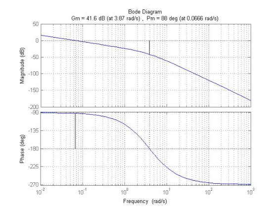
from the above plot, it is observed that the gain margin is 41.6 dB and the phase margin is 88 deg.
gain margin = 10^(41.6/20) = 120.2264 (absolute value).
for gain K = 122.2264 the loop becomes marginally stable and this gain is called critical gain Kc.
Let's plot the root locus to show that the closed-loop poles are purely imaginary for K = Kc = 122.2264.

From the root locus plot, it is observed that for K = 122.2264 the roots are purely imaginary.
Add Answer to:
Let G,()+3s+5) , K-1 and Ge 1 I Determine the loop transfer function L(s)-KG.G. Use 'margin' command in matlab to generate the Bode Plot for L(s). (a) What are its gain and phase margins (the...
Q.3(a) Transfer function model of a plant is, G(s) The controller is Ge(s)-K, where K is a constant. Find the value of K such that steady-state error for unit ramp input is 0.1. Find the gain margin...
 Q.3(a) Transfer function model of a plant is, G(s) The controller is Ge(s)-K, where K is a constant. Find the value of K such that steady-state error for unit ramp input is 0.1. Find the gain margin and the phase mar gin (6 marks) (b) What are the effects on gain margin, phase margin and steady-state error, if the gain K is increased? (3 marks (c) Can the closed loop be unstable if the controller of Q.3(a) is implemented digi...
Consider the following closed-loop system, in which the plant model is P(s) = elave R()2-CO POTY()...
 Consider the following closed-loop system, in which the plant model is P(s) = elave R()2-CO POTY() a) Assume C(s) = K. Determine the range of K for which the closed-loop system is stable via: (1.) the routh-hurwitz stability criteria, (ii.) the margin() command in Matlab, and (lii.) the rlocus command in Matlab. b) Assume a proportional controller of C(s) = K = 40, and a time delay T, located between the controller and plant. Determine the maximum T, value that...
Question 6 The open-loop transfer function G(s) of a control system is given as G(8)- s(s+2)(s +5...
 Question 6 The open-loop transfer function G(s) of a control system is given as G(8)- s(s+2)(s +5) A proportional controller is used to control the system as shown in Figure 6 below: Y(s) R(s) + G(s) Figure 6: A control system with a proportional controller a) Assume Hp(s) is a proportional controller with the transfer function H,(s) kp. Determine, using the Routh-Hurwitz Stability Criterion, the value of kp for which the closed-loop system in Figure 6 is marginally stable. (6...
Y(s) C(s) G(s) R(S) Figure 1: Closed-loop system Q2 Consider the setup in Figure 1 with S s1 (i) ...
 Y(s) C(s) G(s) R(S) Figure 1: Closed-loop system Q2 Consider the setup in Figure 1 with S s1 (i) Design a K,τ, α in the lead compensator 1TOS so that the closed-loop system shown in Figure 1 has a steady state error of.0 for a unit ramp reference input at R and a phase margin of about 45 degrees K, α, τ without Bode plots. When you add phase with the lead compensator add an additional 10 degrees of phase....
The Bode plots for a plant, G(s), used in a unity feedback system are shown in Figure P10.7. Do the following: Find the gain margin, phase margin, zero dB frequency, 180° frequency, and the closed-l...
 The Bode plots for a plant, G(s), used in a unity feedback
system are shown in Figure P10.7. Do the following:
Find the gain margin, phase margin, zero dB frequency, 180°
frequency, and the closed-loop bandwidth.
Use your results in Part a to estimate the damping ratio,
percent overshoot, settling time, and peak time.
ANSWERS GIVEN BY PROFESSOR
1. Gain margin = 20dB, Phase margin = 55 deg, Zero dB frequency
= 1rad/s, 180deg frequency = 4.5rad/s, bandwidth (-7dB) closed-loop...
The Bode plots for a plant, G(s), used in a unity feedback
system are shown in Figure P10.7. Do the following:
Find the gain margin, phase margin, zero dB frequency, 180°
frequency, and the closed-loop bandwidth.
Use your results in Part a to estimate the damping ratio,
percent overshoot, settling time, and peak time.
ANSWERS GIVEN BY PROFESSOR
1. Gain margin = 20dB, Phase margin = 55 deg, Zero dB frequency
= 1rad/s, 180deg frequency = 4.5rad/s, bandwidth (-7dB) closed-loop...
A second-order process is described by its transfer function G(s) = (s+1)(843) and a PI controlle...
 A second-order process is described by its transfer function G(s) = (s+1)(843) and a PI controller by Consider feedback control with unit feedback gain as shown in Figure 1 A disturbance D(s) exists, and to achieve zero steady-state error, a small integral component is applied. Technical limitations restrict the controller gain kp to values of 0.2 or less. The goal is to examine the influence of the controller parameter k on the dynamic response. D(s) Controller Process X(s) Y(s) Figure...
Problem (4): Sketch the root locus plot for a system, whose transfer function are given by 10 K (s2 +3 s+7) the complex poles. G(s) (s +3) i) Determine the joo -axis crossing, breakaway point and the...
 Problem (4): Sketch the root locus plot for a system, whose transfer function are given by 10 K (s2 +3 s+7) the complex poles. G(s) (s +3) i) Determine the joo -axis crossing, breakaway point and the angle of departure from (i) Determine the value of the gain for which the closed loop system will have a pole at (-10)
Problem (4): Sketch the root locus plot for a system, whose transfer function are given by 10 K (s2 +3...
Problem (4): Sketch the root locus plot for a system, whose transfer function are given by 10 K (s2 +3 s+7) the complex poles. G(s) (s +3) i) Determine the joo -axis crossing, breakaway point and the angle of departure from (i) Determine the value of the gain for which the closed loop system will have a pole at (-10)
Problem (4): Sketch the root locus plot for a system, whose transfer function are given by 10 K (s2 +3...
 Q.3(a) Transfer function model of a plant is, G(s) The controller is Ge(s)-K, where K is a constant. Find the value of K such that steady-state error for unit ramp input is 0.1. Find the gain margin and the phase mar gin (6 marks) (b) What are the effects on gain margin, phase margin and steady-state error, if the gain K is increased? (3 marks (c) Can the closed loop be unstable if the controller of Q.3(a) is implemented digi...
 Consider the following closed-loop system, in which the plant model is P(s) = elave R()2-CO POTY() a) Assume C(s) = K. Determine the range of K for which the closed-loop system is stable via: (1.) the routh-hurwitz stability criteria, (ii.) the margin() command in Matlab, and (lii.) the rlocus command in Matlab. b) Assume a proportional controller of C(s) = K = 40, and a time delay T, located between the controller and plant. Determine the maximum T, value that...
 Question 6 The open-loop transfer function G(s) of a control system is given as G(8)- s(s+2)(s +5) A proportional controller is used to control the system as shown in Figure 6 below: Y(s) R(s) + G(s) Figure 6: A control system with a proportional controller a) Assume Hp(s) is a proportional controller with the transfer function H,(s) kp. Determine, using the Routh-Hurwitz Stability Criterion, the value of kp for which the closed-loop system in Figure 6 is marginally stable. (6...
 Y(s) C(s) G(s) R(S) Figure 1: Closed-loop system Q2 Consider the setup in Figure 1 with S s1 (i) Design a K,τ, α in the lead compensator 1TOS so that the closed-loop system shown in Figure 1 has a steady state error of.0 for a unit ramp reference input at R and a phase margin of about 45 degrees K, α, τ without Bode plots. When you add phase with the lead compensator add an additional 10 degrees of phase....
 The Bode plots for a plant, G(s), used in a unity feedback
system are shown in Figure P10.7. Do the following:
Find the gain margin, phase margin, zero dB frequency, 180°
frequency, and the closed-loop bandwidth.
Use your results in Part a to estimate the damping ratio,
percent overshoot, settling time, and peak time.
ANSWERS GIVEN BY PROFESSOR
1. Gain margin = 20dB, Phase margin = 55 deg, Zero dB frequency
= 1rad/s, 180deg frequency = 4.5rad/s, bandwidth (-7dB) closed-loop...
The Bode plots for a plant, G(s), used in a unity feedback
system are shown in Figure P10.7. Do the following:
Find the gain margin, phase margin, zero dB frequency, 180°
frequency, and the closed-loop bandwidth.
Use your results in Part a to estimate the damping ratio,
percent overshoot, settling time, and peak time.
ANSWERS GIVEN BY PROFESSOR
1. Gain margin = 20dB, Phase margin = 55 deg, Zero dB frequency
= 1rad/s, 180deg frequency = 4.5rad/s, bandwidth (-7dB) closed-loop...
 A second-order process is described by its transfer function G(s) = (s+1)(843) and a PI controller by Consider feedback control with unit feedback gain as shown in Figure 1 A disturbance D(s) exists, and to achieve zero steady-state error, a small integral component is applied. Technical limitations restrict the controller gain kp to values of 0.2 or less. The goal is to examine the influence of the controller parameter k on the dynamic response. D(s) Controller Process X(s) Y(s) Figure...
 Problem (4): Sketch the root locus plot for a system, whose transfer function are given by 10 K (s2 +3 s+7) the complex poles. G(s) (s +3) i) Determine the joo -axis crossing, breakaway point and the angle of departure from (i) Determine the value of the gain for which the closed loop system will have a pole at (-10)
Problem (4): Sketch the root locus plot for a system, whose transfer function are given by 10 K (s2 +3...
Problem (4): Sketch the root locus plot for a system, whose transfer function are given by 10 K (s2 +3 s+7) the complex poles. G(s) (s +3) i) Determine the joo -axis crossing, breakaway point and the angle of departure from (i) Determine the value of the gain for which the closed loop system will have a pole at (-10)
Problem (4): Sketch the root locus plot for a system, whose transfer function are given by 10 K (s2 +3...
Most questions answered within 3 hours.
-
An MNE is this kind of industry when competition in one country
is essentially independent of...
asked 6 minutes ago -
. For this set of questions, determine what
proportion of a normal distribution is located betweeneach...
asked 41 minutes ago -
A college student is employed as a door-to-door newspaper
salesman. Historical data suggests that the student...
asked 1 hour ago -
MATLAB HW 11 problem using Switch Case and Input commands
Write a script file that calculates...
asked 1 hour ago -
Considering gravitational time dilation, calculate the time that
passes in Earth’s surface while 1 hour passes...
asked 1 hour ago -
Minitab Problem: Take the Lake Hume June rainfall data and find
use the processes outlined in...
asked 2 hours ago -
X Company is trying to decide whether to continue using old
equipment to make Product A...
asked 2 hours ago -
IN PYTHON ONLY !! Program 2: Re-work
program #5 (WeeklyHours) from the previous assignment such that...
asked 3 hours ago -
The average length of time between arrivals at a turnpike
toll-booth is 26 seconds. What is...
asked 5 hours ago -
(a) A piston at 6.1 atm contains a gas that occupies a volume of
3.5 L....
asked 6 hours ago -
Please answer true or false. Words
cannot be changed or added in to make it true...
asked 6 hours ago -
An empty test tube weighs 15.923 grams. Then,
MgCl2•6H2O is added into the test tube. After...
asked 6 hours ago