
Homework Answers
Add Answer to:
02. 10 pts. Find a differential equation model for each of the systems. No frietion 10 pts. Clearly identify the in...
02. 10 pts. Find a differential equation model for each of the systems. No frietion 10 pts. Clearly identify the in...
 02. 10 pts. Find a differential equation model for each of the systems. No frietion 10 pts. Clearly identify the input, the output, the sate variables, the steady state response to a constant input of 1, and the order of the system. b) 10 pts. Find a differential equation model for each of the systems between the input voltage and output electrical charge q Note: q Jidt 10 pts. Compare the model to that of a mass-damper-spring system, explain the...
Matlab Homework #4: Matlab Linear Systems Simulation 1.) Obtain the differential equation for the...
 Matlab Homework #4: Matlab Linear Systems Simulation 1.) Obtain the differential equation for the mechanical system shown below bi FLR) orce CN) voltege ) 2.) Obtain the differential equation for the electrical system shown below shown below OAF 3.) Find the transfer functions corresponding to the differential equations found in questions I and 2 the 4) Let the input force applied to the block of the mechanical system be zero U)-のThe initial conditions are y(0) = 10 cm and dy(0)d-0....
Show a sketch clearly labeling all of the voltages and currents, and determine the governing differential...
 Show a sketch clearly labeling all of the voltages and
currents, and determine the governing differential equation as
indicated.
please show steps
6. The electro-mechanical system shown below consists of an electric motor with input voltage V which drives inertia I in the mechanical system (see torque T). Find the governing differential equations of motion for this electro-mechanical system in terms of the input voltage to the motor and output displacement y. Electrical System Vbas -Motor Motor Input Voltage bMotor...
Show a sketch clearly labeling all of the voltages and
currents, and determine the governing differential equation as
indicated.
please show steps
6. The electro-mechanical system shown below consists of an electric motor with input voltage V which drives inertia I in the mechanical system (see torque T). Find the governing differential equations of motion for this electro-mechanical system in terms of the input voltage to the motor and output displacement y. Electrical System Vbas -Motor Motor Input Voltage bMotor...
System and computer engineering Model the dynamic systems in STAT VARIABLE form define the order of...
 System and computer engineering
Model the dynamic systems in STAT VARIABLE form
define the order of the system first. Then dram simulation
diagram
Model the following dynamic systems in state variable form. Clearly define the energy storage devices and the corresponding state variables which define the energy in each device. Define the order of the system. Draw the simulation diagram for each system. 4.Input is e(t) Output is edt) e Le)
System and computer engineering
Model the dynamic systems in STAT VARIABLE form
define the order of the system first. Then dram simulation
diagram
Model the following dynamic systems in state variable form. Clearly define the energy storage devices and the corresponding state variables which define the energy in each device. Define the order of the system. Draw the simulation diagram for each system. 4.Input is e(t) Output is edt) e Le)
a) [15 marks] Write the differential equations that describe the behavior of the electrical system shown...
 a) [15 marks] Write the differential equations that describe the behavior of the electrical system shown in Figure 1. Assume that all electrical components behave linearly. Note that v(t) is an external input voltage signal, and vi(t) is the output voltage signal, respectively. 0000 1H 1Ω 1Ω M v(t) Figure 1. Electrical network for question 1. Use the currents ij, iz, and iz which flow through the inductors next to the red, green, and blue arrows, respectively, as the key...
The dynamics of a spring-damper-mass system is defined by the following differential equation, č + 4€...
 The dynamics of a spring-damper-mass system is defined by the following differential equation, č + 4€ + 5x = f(t),x(0) = 1, *(0) = 2, where f(t) is a step input with magnitude of 10, i.e. f(t)=10-1(t). Find the solution x(t) of the differential equation using Laplace transformation method.
... Metro by T-Mobile 11:02 PM X MECH_371_Proble... E .. MECH 371 Spring 2020: Problem Set...
 ... Metro by T-Mobile 11:02 PM X MECH_371_Proble... E .. MECH 371 Spring 2020: Problem Set 3 (/ ) of the systems assuming zero initial conditions 1. Determine the transfer function described by (0)+(1) = 3x(1)+i(1) 2. Consider the system H(S)=7+45+3 (a) Calculate the poles anders of the system (b) Calculate the wep response 3. Determine the transfer function V_ (Assuming zero initial conditions _(s) for the following electrical circuit systems iO +40 4. Consider the system MW f(t) :...
Problem # 1 For each system Derive the differential equation which describes the system. Use Laplace Trans form to...
 Problem # 1 For each system Derive the differential equation which describes the system. Use Laplace Trans form to find the Transfer Function. Specify the number of the Poles and Zeros and the value of the Gain. Determine the system's order both based on the Transfer Function and the number of the energy storage elements. Draw the Block Diagram with Input and Output C. Liquid Level System; assume q is the input and h3 is the output ! Ay Ry...
Question 5 Following differential equations defines input-output relationships of a system with y as output and...
 Question 5 Following differential equations defines input-output relationships of a system with y as output and r as inputs. d’yı + dy 2 + y, + 5 y, = 10 r, dt ? dt. dy 2 + 1 + 7y, = 8r2 dt dt at a) Define suitable state variables and find the state equation and output equation. [8marks] b) Find system matrix (A), input matrix (B) and output matrix (C). [5marks] c) Draw the state space diagram and find...
Problem 2: Transfer Functions of Mechanical Systems. (20 Points) A model sketch for a two-mass mechanical...
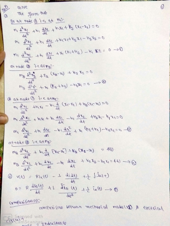
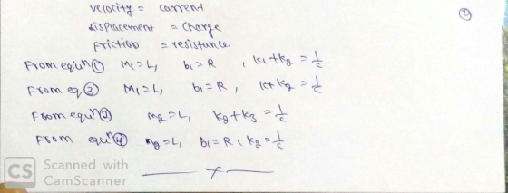
 Problem 2: Transfer Functions of Mechanical Systems. (20 Points) A model sketch for a two-mass mechanical system subjected to fluctuations (t) at the wall is provided in figure 2. Spring k, is interconnected with both spring ka and damper Os at the nodal point. The independent displacement of mass m is denoted by 1, the independent displacement of mass m, is denoted by r2, and the independent displacement of the node is denoted by ra. Assume a linear force-displacement/velocity relationship...
 02. 10 pts. Find a differential equation model for each of the systems. No frietion 10 pts. Clearly identify the input, the output, the sate variables, the steady state response to a constant input of 1, and the order of the system. b) 10 pts. Find a differential equation model for each of the systems between the input voltage and output electrical charge q Note: q Jidt 10 pts. Compare the model to that of a mass-damper-spring system, explain the...
 Matlab Homework #4: Matlab Linear Systems Simulation 1.) Obtain the differential equation for the mechanical system shown below bi FLR) orce CN) voltege ) 2.) Obtain the differential equation for the electrical system shown below shown below OAF 3.) Find the transfer functions corresponding to the differential equations found in questions I and 2 the 4) Let the input force applied to the block of the mechanical system be zero U)-のThe initial conditions are y(0) = 10 cm and dy(0)d-0....
 Show a sketch clearly labeling all of the voltages and
currents, and determine the governing differential equation as
indicated.
please show steps
6. The electro-mechanical system shown below consists of an electric motor with input voltage V which drives inertia I in the mechanical system (see torque T). Find the governing differential equations of motion for this electro-mechanical system in terms of the input voltage to the motor and output displacement y. Electrical System Vbas -Motor Motor Input Voltage bMotor...
Show a sketch clearly labeling all of the voltages and
currents, and determine the governing differential equation as
indicated.
please show steps
6. The electro-mechanical system shown below consists of an electric motor with input voltage V which drives inertia I in the mechanical system (see torque T). Find the governing differential equations of motion for this electro-mechanical system in terms of the input voltage to the motor and output displacement y. Electrical System Vbas -Motor Motor Input Voltage bMotor...
 System and computer engineering
Model the dynamic systems in STAT VARIABLE form
define the order of the system first. Then dram simulation
diagram
Model the following dynamic systems in state variable form. Clearly define the energy storage devices and the corresponding state variables which define the energy in each device. Define the order of the system. Draw the simulation diagram for each system. 4.Input is e(t) Output is edt) e Le)
System and computer engineering
Model the dynamic systems in STAT VARIABLE form
define the order of the system first. Then dram simulation
diagram
Model the following dynamic systems in state variable form. Clearly define the energy storage devices and the corresponding state variables which define the energy in each device. Define the order of the system. Draw the simulation diagram for each system. 4.Input is e(t) Output is edt) e Le)
 a) [15 marks] Write the differential equations that describe the behavior of the electrical system shown in Figure 1. Assume that all electrical components behave linearly. Note that v(t) is an external input voltage signal, and vi(t) is the output voltage signal, respectively. 0000 1H 1Ω 1Ω M v(t) Figure 1. Electrical network for question 1. Use the currents ij, iz, and iz which flow through the inductors next to the red, green, and blue arrows, respectively, as the key...
 The dynamics of a spring-damper-mass system is defined by the following differential equation, č + 4€ + 5x = f(t),x(0) = 1, *(0) = 2, where f(t) is a step input with magnitude of 10, i.e. f(t)=10-1(t). Find the solution x(t) of the differential equation using Laplace transformation method.
 ... Metro by T-Mobile 11:02 PM X MECH_371_Proble... E .. MECH 371 Spring 2020: Problem Set 3 (/ ) of the systems assuming zero initial conditions 1. Determine the transfer function described by (0)+(1) = 3x(1)+i(1) 2. Consider the system H(S)=7+45+3 (a) Calculate the poles anders of the system (b) Calculate the wep response 3. Determine the transfer function V_ (Assuming zero initial conditions _(s) for the following electrical circuit systems iO +40 4. Consider the system MW f(t) :...
 Problem # 1 For each system Derive the differential equation which describes the system. Use Laplace Trans form to find the Transfer Function. Specify the number of the Poles and Zeros and the value of the Gain. Determine the system's order both based on the Transfer Function and the number of the energy storage elements. Draw the Block Diagram with Input and Output C. Liquid Level System; assume q is the input and h3 is the output ! Ay Ry...
 Question 5 Following differential equations defines input-output relationships of a system with y as output and r as inputs. d’yı + dy 2 + y, + 5 y, = 10 r, dt ? dt. dy 2 + 1 + 7y, = 8r2 dt dt at a) Define suitable state variables and find the state equation and output equation. [8marks] b) Find system matrix (A), input matrix (B) and output matrix (C). [5marks] c) Draw the state space diagram and find...
 Problem 2: Transfer Functions of Mechanical Systems. (20 Points) A model sketch for a two-mass mechanical system subjected to fluctuations (t) at the wall is provided in figure 2. Spring k, is interconnected with both spring ka and damper Os at the nodal point. The independent displacement of mass m is denoted by 1, the independent displacement of mass m, is denoted by r2, and the independent displacement of the node is denoted by ra. Assume a linear force-displacement/velocity relationship...
Most questions answered within 3 hours.
-
At December 31, 2020, Pharoah Company has outstanding three
long-term debt issues. The first is a...
asked 23 seconds ago -
Life requires energy. Use what you know about the energy
transformations that occur in animal cells...
asked 5 minutes ago -
Improving access to medical care has been a challenge in the
U.S. health care system. How...
asked 6 minutes ago -
Engineers must consider the breadths of male heads when
designing helmets. The company researchers have determined...
asked 36 minutes ago -
In the Williamson Ether Synthesis of Phenacetin from
Acetaminophen, sodium methoxide in methanol and 100% ethanol...
asked 41 minutes ago -
If the spin of the earth suddenly changed to spin in the
opposite direction, what effect...
asked 55 minutes ago -
An orb weaver spider with a mass of 0.23 grams hangs vertically
by one of its...
asked 51 minutes ago -
Determine the sample size required to estimate the mean score on
a standardized test within
2...
asked 1 hour ago -
The idea that one can remain relatively 'anonymous' on the
internet if they so choose, for...
asked 1 hour ago -
In the reaction of N2 and H2 to produce
NH3, how many moles of H2 will...
asked 1 hour ago -
When a certain coin is flipped, the probability of
obtaining a tails is 0.55. Which of...
asked 59 minutes ago -
Can you show how a sulfonic acid group
is introduced into an aromatic ring by Friedal...
asked 1 hour ago