
Homework Answers
Add Answer to:
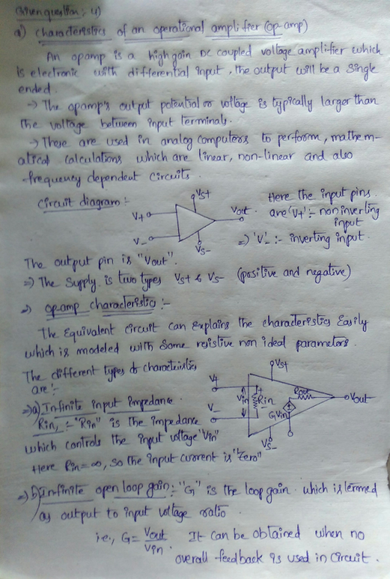
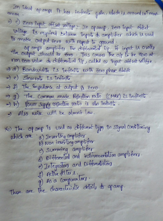
i would appriciate your help. thanks Question 4-(20 marks) (a) Briefly describe the characteristics of an operationa...
The level ho of liquid in a vertical cylindrical tank as shown in Figure 4 is related to the infl...
 please answer all of part i really need them ASAP ...
The level ho of liquid in a vertical cylindrical tank as shown in Figure 4 is related to the inflow of liquid qi by the time domain equation d h dt where τ RLGL, the steady state gain of the system is G RL/pg and the tank capacitance, inlet ine ho outlet vave Tank Figure 4: Tank Level Process (a) You carry out some measurements on the tank and...
please answer all of part i really need them ASAP ...
The level ho of liquid in a vertical cylindrical tank as shown in Figure 4 is related to the inflow of liquid qi by the time domain equation d h dt where τ RLGL, the steady state gain of the system is G RL/pg and the tank capacitance, inlet ine ho outlet vave Tank Figure 4: Tank Level Process (a) You carry out some measurements on the tank and...
Question 1 (10 marks) Liquid flows into a tank and is heated by steam delivered to a jacket on th...
 Question 1 (10 marks) Liquid flows into a tank and is heated by steam delivered to a jacket on the tank (Figure 1). The heated liquid then flows out of the tank through a drain valve. The temperature of the heated liquid is maintained by a closed loop feedback temperature control system. The temperature of the heated liquid is measured by an RTD temperature transmitter which feeds a signal back toa controller mounted in a control room. The output from...
Question 1 (10 marks) Liquid flows into a tank and is heated by steam delivered to...
 Question 1 (10 marks) Liquid flows into a tank and is heated by steam delivered to a jacket on the tank (Figure 1). The heated liquid then flows out of the tank through a drain valve. The temperature of the heated liquid is maintained by a closed loop feedback temperature control system. The temperature of the heated liquid is measured by an RTD temperature transmitter which feeds a signal back toa controller mounted in a control room. The output from...
A tank has an inlet flow of 20 LPM and steady height inside the tank is...
 A tank has an inlet flow of 20 LPM and steady height inside the tank is 1 m. Assuming the area of the tank as 1 sq. m, determine the valve resistance, if the outflow is a linear function of the tank height. If the transfer function is a first order, find the process gain and time constant. a) Determine the change in the tank level with a step change in input of 20%. b) Determine the change in the...
Question A1 A single tank process has first order dynamics. When the inlet flow rate is...
 Question A1 A single tank process has first order dynamics. When the inlet flow rate is chosen as the input and the level as the output, the transfer function is as follows. 5 G(s) - H(s) 2. (S) S +1 91(t) h(t) *7 q:(0) q2(t) Fig. Q.Al schematic of the liquid level process (a) Determine the system constant t and steady state gain K. [6 marks] (b) For a unit step input q, (t) = 1(1), determine the time response...
Question 2 a) The following diagram show a liquid-level storage tank with q, and qi is...
 Question 2 a) The following diagram show a liquid-level storage tank with q, and qi is the inlet and outlet volumetric flow rate of the tank. Ri is the resistance valve whereas Hi is the liquid level of the tank. Find the transfer function relating change in level, Qi', to the changes in flow rate into the tank, Q' (State your assumption) (10 marks) b) An electrically heated process is known to exhibit second order dynamics. The heater input change...
help plzzz Question 4-(12 marks) At 20°C, an input of 0 m3/s to a flow transmitter produces an output of 4 mA and an...
 help plzzz
Question 4-(12 marks) At 20°C, an input of 0 m3/s to a flow transmitter produces an output of 4 mA and an input of 15 m3/s produces an output of 20 mA. The transmitter has a thermal zero shift of 0.0015 mA/C and a thermal sensitivity shift of 4 x 10 (mA/( m3/s)/ C. Determine the following: (a) The sensitivity of the transmitter at 20°C. (b) The output from the transmitter at an input flow rate of 10...
help plzzz
Question 4-(12 marks) At 20°C, an input of 0 m3/s to a flow transmitter produces an output of 4 mA and an input of 15 m3/s produces an output of 20 mA. The transmitter has a thermal zero shift of 0.0015 mA/C and a thermal sensitivity shift of 4 x 10 (mA/( m3/s)/ C. Determine the following: (a) The sensitivity of the transmitter at 20°C. (b) The output from the transmitter at an input flow rate of 10...
The figure for 4-52 is the image below. Solve problem B-4-10. Then answer the following: 1. If the head h is the input...
 The figure for 4-52 is the image below.
Solve problem B-4-10. Then answer the following: 1. If the head h is the input to the hydraulic controller and the output from the controller is y, derive the transfer function of the controller? 2. What is the control action of this controller? Screen Shot 2019-06-03 at 10.49.13 PM Q Search B-4-10. Consider the liquid-level control Figure 4-52. The inlet valve is controlled by a hydraulic integral controller. Assume that the steady-state...
The figure for 4-52 is the image below.
Solve problem B-4-10. Then answer the following: 1. If the head h is the input to the hydraulic controller and the output from the controller is y, derive the transfer function of the controller? 2. What is the control action of this controller? Screen Shot 2019-06-03 at 10.49.13 PM Q Search B-4-10. Consider the liquid-level control Figure 4-52. The inlet valve is controlled by a hydraulic integral controller. Assume that the steady-state...
Question 2 2.1 Consider a stirred tank heater which is characterised by the following equation: z4 pCpE The tank ha...
 Question 2 2.1 Consider a stirred tank heater which is characterised by the following equation: z4 pCpE The tank has a constant liquid volume V, 50 litres and a constant volumetric flow rate of F 10 litres/minute. For liquid water, the other parameters are pCp 1 kcal/ litre.°C. Determine the process gain and time constant of the system. 2.1.1 2.1.2 Write down the transfer function of the process. (9) 2.1.3 Determine the time-domain output of this process to a step...
My question is Problem 11.4-8 Thanks for your help! 11.4-8. Consider the third-order continuous-time LTI system...
 My question is Problem 11.4-8
Thanks for your help!
11.4-8. Consider the third-order continuous-time LTI system * = Ax + Bu y = Cx 102 with A = To 0 Lo 2 0 -8 07 3 , B = -6] 0 , and C = [1 0 0]. Using Q = [800] 0 6 0, LO 0 4 R = 1.5 (a) First design a LQ controller for this continuous time-system using the MATLAB function iqr. Let the optimal controller...
My question is Problem 11.4-8
Thanks for your help!
11.4-8. Consider the third-order continuous-time LTI system * = Ax + Bu y = Cx 102 with A = To 0 Lo 2 0 -8 07 3 , B = -6] 0 , and C = [1 0 0]. Using Q = [800] 0 6 0, LO 0 4 R = 1.5 (a) First design a LQ controller for this continuous time-system using the MATLAB function iqr. Let the optimal controller...
 please answer all of part i really need them ASAP ...
The level ho of liquid in a vertical cylindrical tank as shown in Figure 4 is related to the inflow of liquid qi by the time domain equation d h dt where τ RLGL, the steady state gain of the system is G RL/pg and the tank capacitance, inlet ine ho outlet vave Tank Figure 4: Tank Level Process (a) You carry out some measurements on the tank and...
please answer all of part i really need them ASAP ...
The level ho of liquid in a vertical cylindrical tank as shown in Figure 4 is related to the inflow of liquid qi by the time domain equation d h dt where τ RLGL, the steady state gain of the system is G RL/pg and the tank capacitance, inlet ine ho outlet vave Tank Figure 4: Tank Level Process (a) You carry out some measurements on the tank and...
 Question 1 (10 marks) Liquid flows into a tank and is heated by steam delivered to a jacket on the tank (Figure 1). The heated liquid then flows out of the tank through a drain valve. The temperature of the heated liquid is maintained by a closed loop feedback temperature control system. The temperature of the heated liquid is measured by an RTD temperature transmitter which feeds a signal back toa controller mounted in a control room. The output from...
 Question 1 (10 marks) Liquid flows into a tank and is heated by steam delivered to a jacket on the tank (Figure 1). The heated liquid then flows out of the tank through a drain valve. The temperature of the heated liquid is maintained by a closed loop feedback temperature control system. The temperature of the heated liquid is measured by an RTD temperature transmitter which feeds a signal back toa controller mounted in a control room. The output from...
 A tank has an inlet flow of 20 LPM and steady height inside the tank is 1 m. Assuming the area of the tank as 1 sq. m, determine the valve resistance, if the outflow is a linear function of the tank height. If the transfer function is a first order, find the process gain and time constant. a) Determine the change in the tank level with a step change in input of 20%. b) Determine the change in the...
 Question A1 A single tank process has first order dynamics. When the inlet flow rate is chosen as the input and the level as the output, the transfer function is as follows. 5 G(s) - H(s) 2. (S) S +1 91(t) h(t) *7 q:(0) q2(t) Fig. Q.Al schematic of the liquid level process (a) Determine the system constant t and steady state gain K. [6 marks] (b) For a unit step input q, (t) = 1(1), determine the time response...
 Question 2 a) The following diagram show a liquid-level storage tank with q, and qi is the inlet and outlet volumetric flow rate of the tank. Ri is the resistance valve whereas Hi is the liquid level of the tank. Find the transfer function relating change in level, Qi', to the changes in flow rate into the tank, Q' (State your assumption) (10 marks) b) An electrically heated process is known to exhibit second order dynamics. The heater input change...
 help plzzz
Question 4-(12 marks) At 20°C, an input of 0 m3/s to a flow transmitter produces an output of 4 mA and an input of 15 m3/s produces an output of 20 mA. The transmitter has a thermal zero shift of 0.0015 mA/C and a thermal sensitivity shift of 4 x 10 (mA/( m3/s)/ C. Determine the following: (a) The sensitivity of the transmitter at 20°C. (b) The output from the transmitter at an input flow rate of 10...
help plzzz
Question 4-(12 marks) At 20°C, an input of 0 m3/s to a flow transmitter produces an output of 4 mA and an input of 15 m3/s produces an output of 20 mA. The transmitter has a thermal zero shift of 0.0015 mA/C and a thermal sensitivity shift of 4 x 10 (mA/( m3/s)/ C. Determine the following: (a) The sensitivity of the transmitter at 20°C. (b) The output from the transmitter at an input flow rate of 10...
 The figure for 4-52 is the image below.
Solve problem B-4-10. Then answer the following: 1. If the head h is the input to the hydraulic controller and the output from the controller is y, derive the transfer function of the controller? 2. What is the control action of this controller? Screen Shot 2019-06-03 at 10.49.13 PM Q Search B-4-10. Consider the liquid-level control Figure 4-52. The inlet valve is controlled by a hydraulic integral controller. Assume that the steady-state...
The figure for 4-52 is the image below.
Solve problem B-4-10. Then answer the following: 1. If the head h is the input to the hydraulic controller and the output from the controller is y, derive the transfer function of the controller? 2. What is the control action of this controller? Screen Shot 2019-06-03 at 10.49.13 PM Q Search B-4-10. Consider the liquid-level control Figure 4-52. The inlet valve is controlled by a hydraulic integral controller. Assume that the steady-state...
 Question 2 2.1 Consider a stirred tank heater which is characterised by the following equation: z4 pCpE The tank has a constant liquid volume V, 50 litres and a constant volumetric flow rate of F 10 litres/minute. For liquid water, the other parameters are pCp 1 kcal/ litre.°C. Determine the process gain and time constant of the system. 2.1.1 2.1.2 Write down the transfer function of the process. (9) 2.1.3 Determine the time-domain output of this process to a step...
 My question is Problem 11.4-8
Thanks for your help!
11.4-8. Consider the third-order continuous-time LTI system * = Ax + Bu y = Cx 102 with A = To 0 Lo 2 0 -8 07 3 , B = -6] 0 , and C = [1 0 0]. Using Q = [800] 0 6 0, LO 0 4 R = 1.5 (a) First design a LQ controller for this continuous time-system using the MATLAB function iqr. Let the optimal controller...
My question is Problem 11.4-8
Thanks for your help!
11.4-8. Consider the third-order continuous-time LTI system * = Ax + Bu y = Cx 102 with A = To 0 Lo 2 0 -8 07 3 , B = -6] 0 , and C = [1 0 0]. Using Q = [800] 0 6 0, LO 0 4 R = 1.5 (a) First design a LQ controller for this continuous time-system using the MATLAB function iqr. Let the optimal controller...
Most questions answered within 3 hours.
-
if we subtract 1000 from 0001 is there overflow? (binary)
asked 5 minutes ago -
Hello, I need help with the function below, The language I am
using is Ocaml
open...
asked 6 minutes ago -
Explain how the presence of glucose represses the gal structural
genes?
asked 14 minutes ago -
For the reaction CaI2+2AgNO3⟶2AgI+Ca(NO3)2 how many grams of
silver iodide, AgI, are produced from 56.5 g...
asked 25 minutes ago -
Write an equation for hydrolysis via acid catalysis.
Using ethyl acetate, ethyl benzoate, ethyl formate or...
asked 33 minutes ago -
Only one graph is needed.
(a) Draw a Supply Curve and the Demand Curve for the...
asked 36 minutes ago -
Fill in the blanks and please show how you arrived at numerical
answers
. The...
asked 36 minutes ago -
91. If the half – life of a sample of radioactive
material is 60 days, what...
asked 43 minutes ago -
White light (380nm-750nm) strikes a diffraction grating (420
lines/mm) at normal incidence. What is the highest-order...
asked 53 minutes ago -
1) Explain what is meant by a good being "excludable."?
2) Explain what is meant by...
asked 52 minutes ago -
I need help with this question:
Describe in detail at least two factors that stimulated American...
asked 59 minutes ago -
Calculate the Boyle temperature for helium assuming it follows
the Berthelot equation of state.
asked 1 hour ago